When I think about creating a system that runs seamlessly, one thing becomes clear — structure matters. True clarity starts with how we organize and represent data. That’s where information structure modeling comes in. It might sound complex at first, but it’s a real game-changer. By modeling information structures effectively, we turn abstract data into meaningful relationships that drive smarter design, improve communication, and make every part of the system work in harmony.
Why Information Structure Modeling Matters
Imagine you have to create a system. In that case the first step is to define everything — i.e. the terms, the data, and the requirements. Hence without a clear structure, this process can get messy fast. Here’s where information structure modeling comes into play.
Information structure modeling isn’t just about listing terms and data. It’s about creating relationships between these elements. For instance, if I’m building a Customer Relationship Management (CRM) system, I need to know what data is relevant to a customer. This isn’t just about creating a list of customer details like name, email, and phone number. Instead, I define each key piece of customer information as an attribute that the system can store, validate, and use consistently. It’s also about understanding how that attribute interacts with other data, what makes it essential, and how the system should handle it.
Glossaries vs. Information Models
Now, let’s talk about glossaries. In requirements engineering, a glossary often serves to define the terms specific to a project. However, this is where the limitations start showing. A glossary, while helpful, is typically just a list. It defines terms, but it doesn’t explain how these terms relate to each other or why they are important.
In contrast, an information model takes this a step further. Not only does it define terms, but it also shows the relationships between them. For example, in a glossary, I might define a “customer” and an “order.” But with an information model, I can also show that a customer can place multiple orders, and each order associates to one customer. This relational aspect is key.
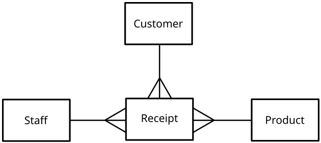
To visualize this, I would suggest using a diagram. A simple Entity-Relationship (ER) diagram could do the trick. It’s a great way to represent entities (like customers and products) and their relationships visually.

If you’re more into the technical side of things, a Unified Modeling Language (UML) class diagram might be even better, as it integrates well with other aspects of system design.
The Role of UML in Information Modeling
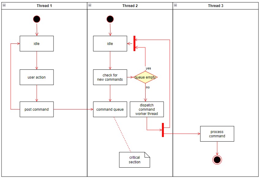
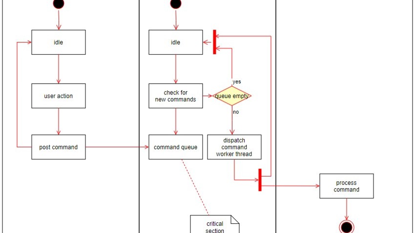
Speaking of UML, let’s delve into why it’s so useful. In essence UML class diagrams are like the Swiss Army knife of information structure modeling. They don’t just stand alone — i.e. they integrate with other diagrams used in system design. This means I can link an activity diagram, which shows how a user interacts with the system, to the underlying information model. This linkage ensures that all views of the system align.

Bridging Gaps and Ensuring Completeness
While creating these models, something interesting often happens. Gaps in the requirements become apparent. Maybe I realize that I’ve overlook a critical piece of data or that the relationships between entities aren’t complete. This is actually a good thing. It’s better to discover these issues while modeling rather than during development.
For instance, while modeling the information structure for a CRM system, I might notice that I haven’t defined what happens if a customer cancels an order. Is the order data deleted, archived, or something else? This prompts me to revisit the requirements, ensuring everything is covered.
A practical way to keep track of these gaps is by using color-coded notes on your diagrams. Red might indicate missing information, while green could signify complete and verified sections. This visual aid helps me stay organized and ensures that no detail is overlooked.
A concrete example
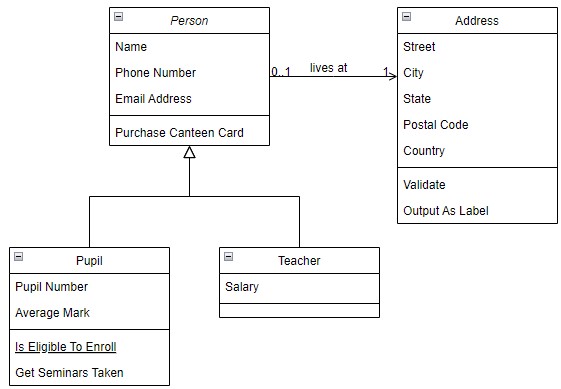
The following UML class diagram contains four classes: Person, Pupil, Teacher and Address. The teacher’s only attribute is her salary. The student has the attributes Pupil Number and Average Mark. Students have the methods or abilities Is Eligible To Entroll and Get Seminars Taken.

Students and teachers are always persons. A person is either a student or a teacher. As a person, the attributes Name, Phone Number and Email Address exist. A person can buy a cafeteria card.
The arrow from left to right indicates that no person or one person can live at an address. The address has the attributes Street, City, State, Postal Code and Country. The methods Validate and Output as Label are associated with it.
Wrapping It Up
In conclusion, information structure modeling is more than just a technical task—it’s the foundation of a successful system. By defining not just the terms but also their relationships, we create a robust structure that guides the entire development process. With tools like UML class diagrams and ER diagrams, I can ensure that every requirement is captured, every relationship is clear, and every potential issue is addressed before it becomes a problem.
Next time you’re diving into a project, remember to give information structure modeling the attention it deserves. Your future self will thank you.
What’s Next?!
Now that you’ve seen how information structure modeling brings clarity and order to complex systems, it’s time to put that knowledge into practice. In my next article, “How to Build a UML Class Diagram with draw.io,” I’ll guide you step by step through creating your own visual model. Discover how to turn abstract ideas into clear, structured diagrams that make your system easy to understand and communicate. Let’s make modeling both practical and enjoyable.
Credits: Example for an Entity Relationship Model by Pluke from Wikimedia Commons under the licence Deed – CC0 1.0 Universal – Creative Commons,
This article covers concepts that are also included in the CPRE certification syllabus.
| Read more about Confluence and How to |
|---|
| Use shortcuts in Confluence Assign a task in Confluence Create a Confluence space from a template Delete a Page in Confluence Create a Confluence page |

