Requirements modeling is a key part of systems engineering. It connects stakeholder needs with system implementation and ensures clarity and consistency. By applying structured methods, it defines the terms and concepts in requirements modeling that shape clear and complete specifications. In this article, I explore these fundamental elements, their relationships, and their importance in building effective and reliable models for complex systems.
What is Requirements Modeling
Requirements modeling is the practice of visually representing project requirements to make them easier to understand, communicate, and manage. In project management, it plays a central role by aligning all stakeholders around a shared vision of the system. Models reveal dependencies, risks, and missing details early on, helping prevent costly misunderstandings later. By using clear diagrams and structures, I can plan, monitor, and control project scope more effectively.
A graphical approach
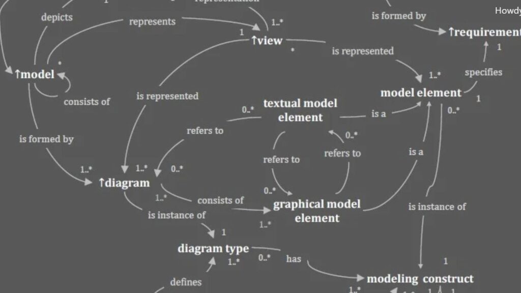
The following shows a semantic network of the basic terms and concepts relevant for requirements modeling. You can find the graphic in the CPRE Advanced Level Requirements Modeling – Handbook (opens a new tab). Moreover the Certified Professional Requirements Engineer Advanced Level Requirements Modeling certificate is part of the curriculum of the International Requirements Engineering Board (IREB).
Modeling language
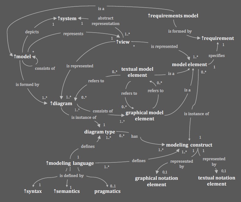
The big picture of a modeling language becomes clear when I look at the concept map shown above. This diagram illustrates how all central terms—such as model, view, diagram, model element, modeling construct, and notation—connect to each other and form a coherent conceptual system. I refer to this concept map throughout this chapter because it visualizes the underlying structure of every modeling language and helps me explain how the discipline fits together.
When I work with models, I always rely on a modeling language. It gives me the vocabulary, rules, and structures I need to express complex ideas with clarity. A modeling language is more than a collection of symbols. It is a complete system that defines how I describe a model, how I interpret it, and how I use it in practice.
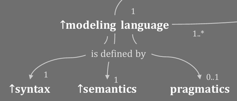
A modeling language consists of syntax, semantics, and pragmatics. These three dimensions ensure that models are not only correct on paper, but also meaningful and useful in real projects. The concept map makes this explicit at the bottom of the diagram, where syntax, semantics, and pragmatics form the foundation of the entire modeling language.
Syntax: How I build valid models
Syntax defines “the rules for constructing the symbols of the language”. It tells me:
- which model elements exist,
- how I may combine them,
- and what structure a correct diagram must follow.
In the concept map, syntax appears at the lower left, connected to the modeling language. This shows that syntax is not isolated. Instead, it defines the shape and structure of modeling constructs and notation elements.
Semantics: What the model elements mean
Semantics defines “the meaning behind the signs and elements”. It gives every element a clear interpretation.
When I model a “Start Event” in BPMN, the semantics tell me that it starts a new process instance. When I draw a UML class, its semantics tell me that it represents a concept with an attribute that captures a key property and with operations that describe behavior. Semantics ensures that different people interpret the same diagram consistently.
In the concept map, semantics sits next to syntax and pragmatics, revealing how it anchors the meaning of every modeling construct and notation element.
Pragmatics: Why I use the model and how it helps me
Pragmatics focuses on “purpose and usefulness”. It reminds me that the value of a model depends on whether it helps someone achieve a goal—something the concept map highlights clearly by placing pragmatics as part of the modeling language’s foundation.
Pragmatics answers questions like:
- Does the model support understanding?
- Does it help stakeholders reason about the system?
- Is the diagram appropriate for the audience?
Pragmatics turns a formally correct model into an effective communication tool.
Models, Views, and Systems: The foundation
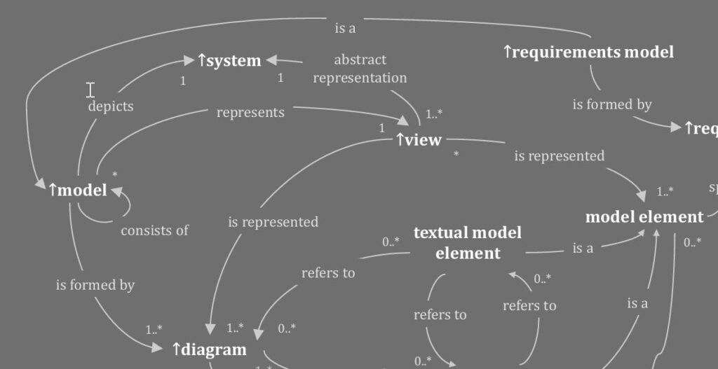
The top of the concept map shows the relationship between system, model, and view.
A model is “an abstract representation of a system”. A view is “a selective excerpt of that model”.
This helps me focus on the parts that matter:
- A process view highlights activities and events.
- A data view highlights structures and relationships.
- A user view highlights interactions.
These relationships in the diagram show the heart of modeling: abstraction, representation, and perspective.
Model Elements: The building blocks of every model
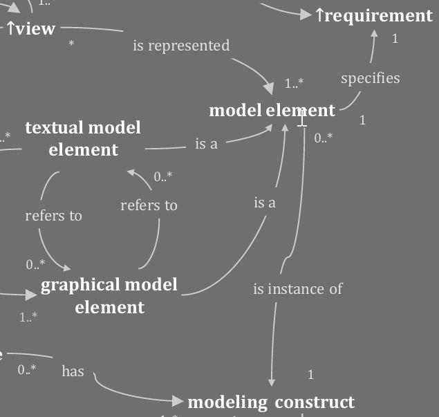
Model elements sit in the center of the concept map. They are the atomic pieces of a model, they can be textual or graphical, they can reference each other, and they form the internal structure of a model.
Their central placement in the diagram reflects their importance: everything else—diagrams, notation, and constructs—exists to represent and connect model elements.
Diagrams and Diagram Types: How I visualize a model
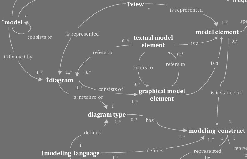
In the concept map, diagrams appear directly below the model. This indicates that “diagrams are visual representations of parts of a model”.
Diagram types define which model elements and relationships I can use. For example:
- BPMN Process Diagram
- UML Class Diagram
- UML Sequence Diagram
Diagram types ensure consistency. They allow me to visualize one coherent perspective. The diagram’s place in the concept map shows how it acts as the bridge between abstract model elements and concrete notation.
Modeling Constructs and Notation Elements
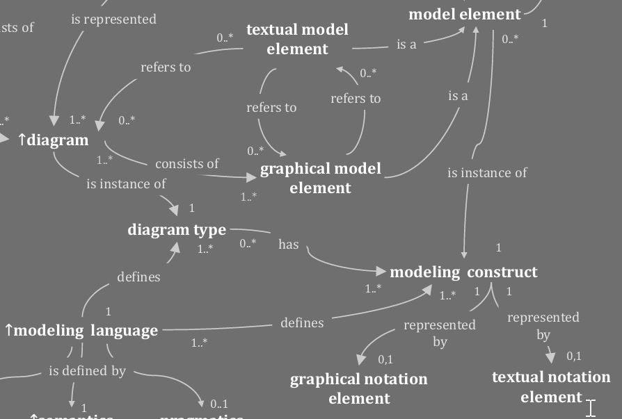
To make constructs visible, I rely on notation. The concept map separates:
- graphical notation elements
- textual notation elements
Both represent modeling constructs. These constructs are the abstract building blocks of the modeling language, like “Activity”, “Class”, “Actor”, or “State”.
The concept map shows this transformation clearly:
modeling construct → represented through → graphical or textual notation element
This is how abstract concepts become visible diagrams.
How everything connects: The modeling language as a system
The concept map gives me the best possible overview. It shows:
- A system is represented by a model.
- A model expresses itself through one or multiple diagrams.
- A diagram uses notation to represent model elements.
- A modeling language defines all these constructs.
- Syntax, semantics, and pragmatics give the language its structure, meaning, and purpose.
This conceptual map is not just academic. It reflects the real-world flow of how I think, how I design, and how I communicate complex systems.
Why a modeling language matters in requirements engineering

With a modeling language, I can:
- reduce ambiguity,
- improve communication,
- validate requirements early,
- structure complex information,
- and create maintainable system descriptions.
The concept map makes this visible: every concept supports clarity, precision, and shared understanding. That is why modeling languages are essential tools in professional requirements engineering.
Conclusion
In conclusion, understanding the terms and concepts in requirements modeling is essential for creating accurate and effective system models. By leveraging the definitions and relationships outlined in the IREB Glossary (opens in new tab) and supplementing them with additional essential terms, requirements modeling becomes a more structured and manageable process. This approach not only aids in maintaining consistency and clarity. It also enhances communication among stakeholders, ultimately contributing to the successful development of a system.
What’s Next?!
Now that you understand how requirements modeling supports clear communication and structure in project management, it’s time to move deeper into software design. Object-oriented principles form the foundation of many modern systems. In my next article, Understanding the Function Principle of Object-Orientation, I explain how objects, classes, and interactions bring models to life in real applications. Click ahead and explore how structure transforms into functionality.
This article covers concepts that are also included in the CPRE certification syllabus.
| More about Requirements Modeling |
|---|
| Context modeling in Requirements Engineering Unleashing the Power of Dynamic View in Requirements Modeling Enhancing Requirements Modeling: Adapting UML and SysML with Stereotypes Information Structure, Dynamics, Quality, and Constraints Views in Requirements Modeling Integrating Textual Requirements in SysML: A Personal Take |