
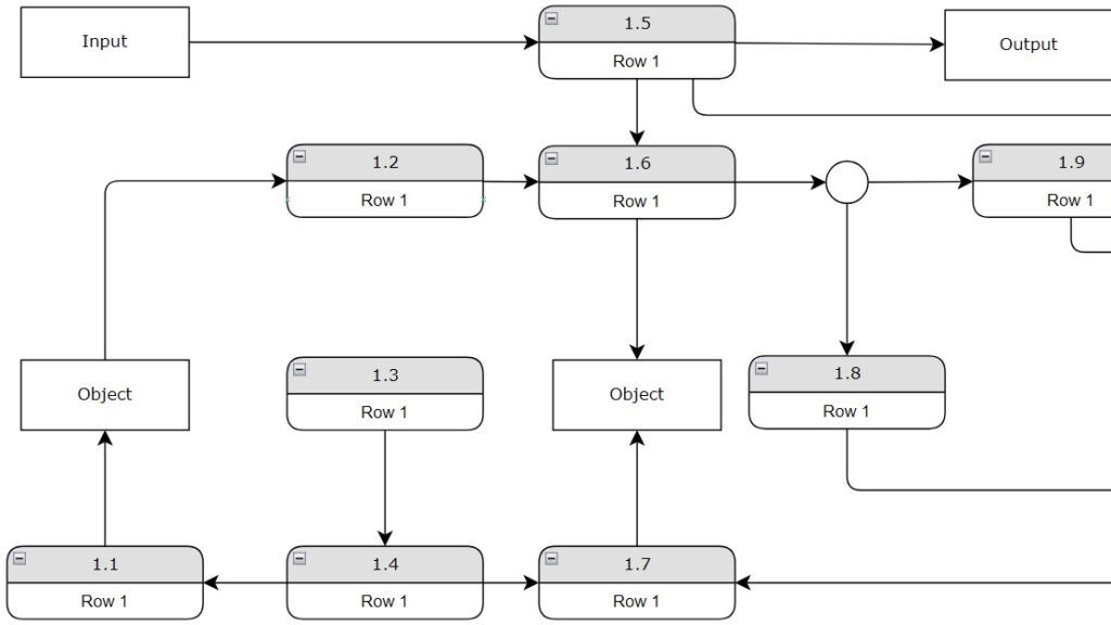
When developing a system, understanding requirements is essential. It’s like constructing a house — the blueprint must come first. I’ve learned that dynamic views in requirements modeling are powerful for illustrating how a system behaves over time. They reveal interactions, processes, and reactions between components. By using dynamic views, we gain a deeper understanding of system logic and performance. Let’s explore how this approach brings models to life and connects design with real behavior.
Dynamic Views Show System Behavior
I use dynamic views when requirements describe behavior rather than only structure.
However, system behavior has several dimensions. Therefore, one diagram type cannot answer every question.
I distinguish five useful perspectives:
- use case view,
- control flow-oriented view,
- data flow-oriented view,
- state-oriented view,
- scenario view.
Each dynamic view focuses on a different aspect of system behavior.
Use Case View
I use a use case view to show which functions a system provides and which external actors interact with them.
The Early Warning System provides a good example. Sensor and Operator interact with functions such as Read sensor data, Update thresholds, Show detailed info, and Acknowledge alarm. In addition, external systems interact with output functions.
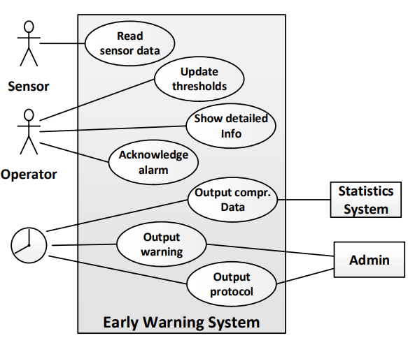
The complete model gives me the overall system context.
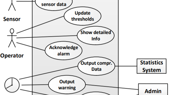
Sometimes, however, I want to focus only on selected actors and use cases. A cropped view can make these connections easier to inspect.
A second example shows the same modeling perspective in another context. Here, Parent/Teacher and Child interact with functions such as Maintain Question, Maintain User, Log On, Game, and Difficulty.
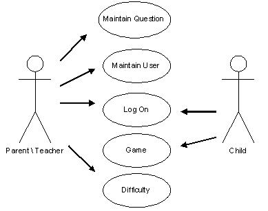
I use the use case view to identify externally visible system functionality and the actors that interact with it.
Control Flow-Oriented View
A control flow-oriented view focuses on execution order.
The simplest case shows functions that follow one another sequentially.

This view tells me that Function 1 comes before Function 2 and Function 2 before Function 3.
However, real behavior often contains decisions, loops, synchronization, or parallel activities. Therefore, I can use a more detailed activity model.
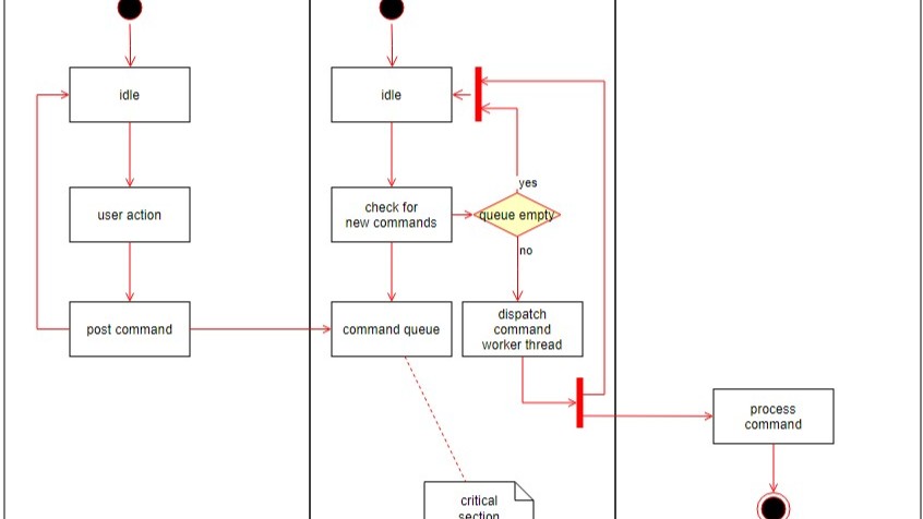
The following diagram also belongs to the control flow-oriented perspective. In the old article, it appeared under the state-oriented view. However, it shows activities and control flows rather than states.
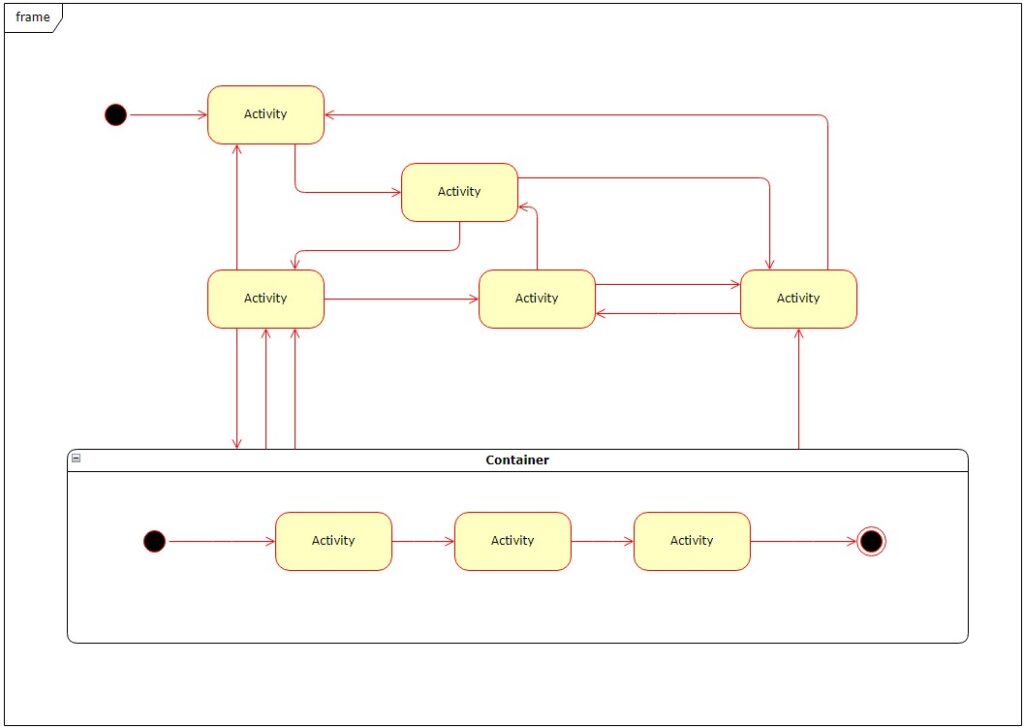
I use control flow views when I need to understand which activity follows another and how execution branches or synchronizes.
Data Flow-Oriented View
A data flow-oriented view answers a different question.
Here, I focus on the information that functions receive and produce.
In the first example, Function 1 receives input a. It then produces flows b and c. Function 2 and Function 3 process these flows and create further outputs.
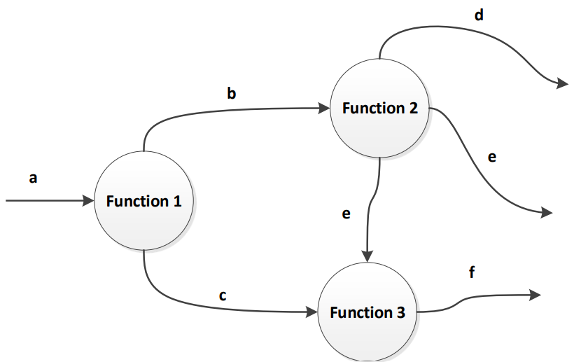
This representation helps me identify dependencies between functions.
A more detailed model can also show external inputs, outputs, objects, functions, and data stores.
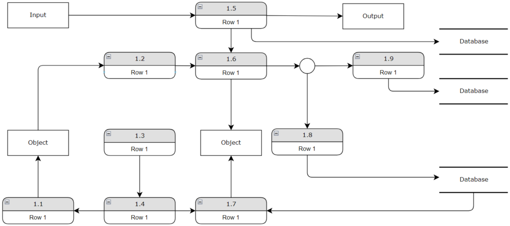
I use data flow views to understand which information functions need, produce, and exchange.
State-Oriented View
A state-oriented view describes how a system or object behaves depending on its current state.
The windshield-wiper example shows this clearly.
The system can be in states such as Start position, Wash, Final wipe, Intermittent Wiping, Normal Wiping, and Fast Wiping.
Events such as Wash selected or Wipe selected trigger transitions. Conditions can further determine which transition occurs.
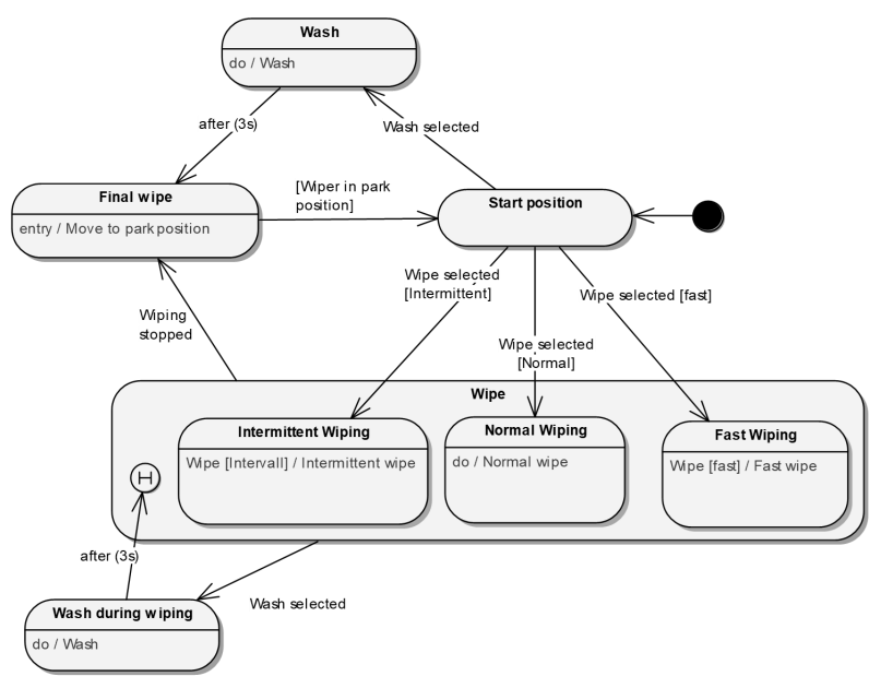
The important difference from control flow is the perspective.
A control flow asks what happens next. A state model asks how the system reacts to an event while it is in a particular state.
I use state-oriented views when required behavior depends on the current state and incoming events.
Scenario View
Finally, I use scenarios to describe one concrete interaction between participants.
A sequence diagram represents these interactions in chronological order.
In the example, two objects exchange dispatch, callback, and return messages.
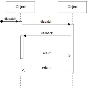
.The scenario does not show every possible system behavior. Instead, it represents one specific interaction path.
I use scenario views when I want to understand how specific participants interact over time.
Choosing the Right Dynamic View
I choose the view according to the question I need to answer.
A use case view shows which functionality actors expect from the system.
A control flow view shows how activities execute.
A data flow view shows how information moves.
A state view shows how behavior depends on states and events.
Finally, a scenario view shows how specific participants interact over time.
I do not look for one universal dynamic model; I choose the view that best exposes the behavior I need to analyze.
Conclusion
Requirements Modeling with Dynamic Views helps me examine system behavior from several complementary perspectives.
Use cases show externally visible functionality. Control-flow models show execution logic. Data-flow models show information dependencies. State models show event-driven reactions. Finally, scenarios show interactions between participants.
Together, these dynamic views help me describe complex behavior without forcing every aspect into one diagram.
What’s Next?!
Now that you know what requirements modeling is and why it’s vital in business analysis, it’s time to look deeper. In my next article, “Unleashing the Power of Dynamic View in Requirements Modeling,” I’ll show how to visualize system behavior over time. Discover how dynamic views bring models to life, reveal hidden dependencies, and make complex systems easier to understand. Let’s continue this journey toward smarter and more effective modeling together.
Explore Requirements Modeling in More Depth
If I want to understand requirements more clearly, I need more than isolated text statements. I need models that show structure, flow, and relationships in a practical way. In the main article on Requirements Modeling, I explore essential Modeling Concepts, Process Modeling with BPMN, and the structural perspective of UML. Together, these topics help me analyze systems more effectively, communicate ideas more clearly, and build a stronger foundation for successful design and implementation.
This article covers concepts that are also included in the CPRE certification syllabus.