
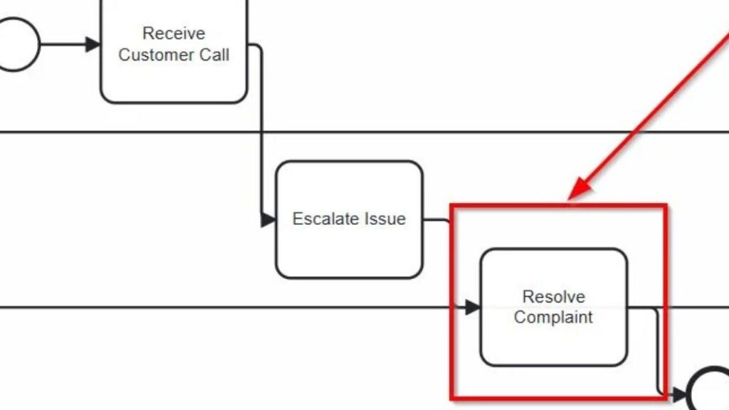
Whenever I model a business process, I want clarity. Especially when it comes to responsibilities. That’s why I use the nesting of BPMN lanes. This technique gives structure. It shows clearly who does what—without overwhelming the diagram. In fact, the nesting of BPMN lanes helps me group roles within departments, making complex processes both readable and precise.
What is BPMN 2.0?
BPMN 2.0 stands for Business Process Model and Notation. It’s the global standard for modeling business processes. I use it because it brings structure to complexity. Moreover, it makes workflows both readable and executable.
BPMN diagrams contain Tasks, Events, and Gateways—called Flow Nodes. I connect these with Sequence Flows. As a result, I get a visual path that mirrors the real process. Everything stays organized and easy to understand. Dig deeper into What is Camunda? and explore BPMN Core Elements with Camunda: My Hands-On Guide for clear insights and practical modeling tips.
Step 1: I Define the Process Participant
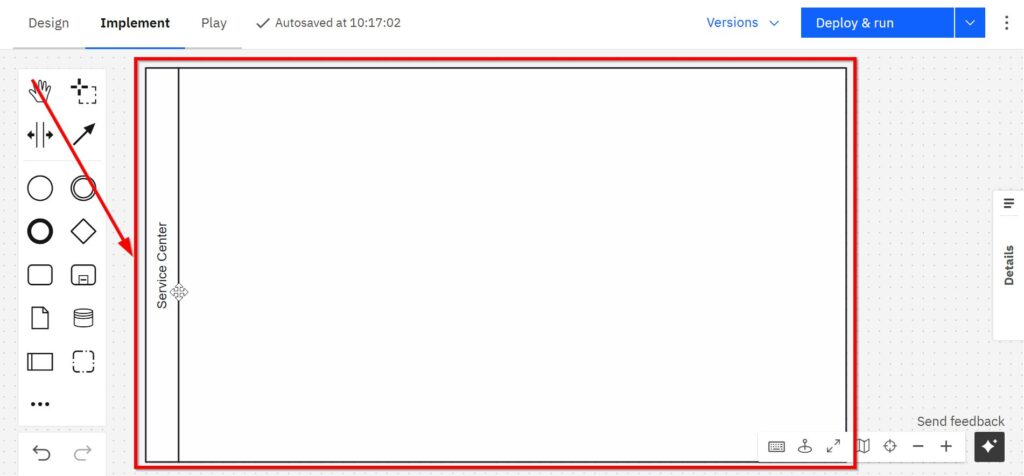
I start with the process boundary. In my example, the participant is the Service Center.
Therefore, I create one Pool and name it Service Center. At this stage, I deliberately leave the internal structure empty. First, I want to establish what belongs to this participant.
Step 2: I Add the Responsibility Areas
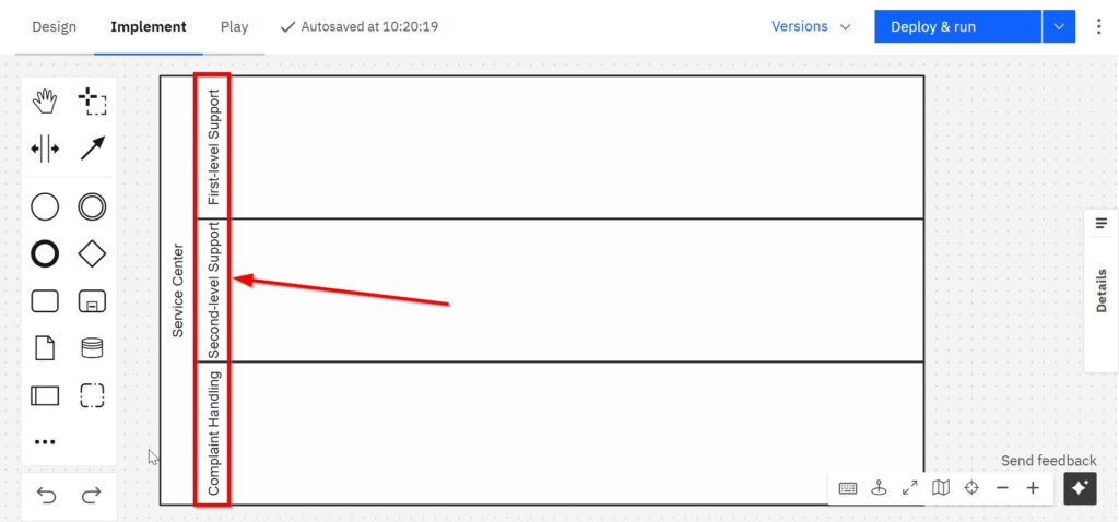
Next, I divide the Service Center into three Lanes:
First-level Support, Second-level Support, and Complaint Handling.
These Lanes make the organizational handovers visible immediately. A reader can now see which part of the Service Center handles each stage of the process.
However, there is an important BPMN distinction here.
The three areas in this example are sibling Lanes, not nested Lanes in the strict BPMN sense.
They all sit on the same hierarchy level inside the Pool. True Lane nesting starts when I subdivide one Lane into additional child Lanes.
For example, I could create a Support Lane and then subdivide it into First-level Support and Second-level Support. That hierarchy would represent actual nesting. Complaint Handling could remain a separate Lane.
I only introduce this additional hierarchy when it communicates something relevant. Otherwise, flat Lanes remain easier to understand.
Step 3: I Place Each Activity with Its Responsible Area
Now I add the process activities.
First-level Support receives the customer call. Second-level Support handles the escalation. Complaint Handling resolves the complaint.
Therefore, I place:
Receive Customer Call in First-level Support.
Escalate Issue in Second-level Support.
Resolve Complaint in Complaint Handling.
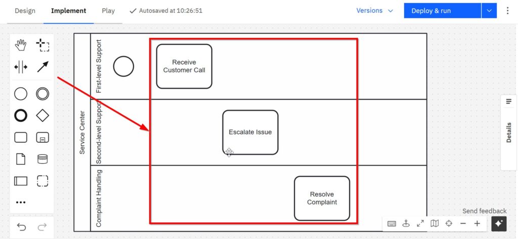
I place every activity completely inside the most specific Lane that represents its responsibility.
This approach makes the model easier to interpret. The reader does not need additional annotations to determine who performs each step.
Step 4: I Connect the Activities with Sequence Flows
After assigning the activities, I connect them.
The process starts in First-level Support. Then Receive Customer Call leads to Escalate Issue. Finally, the process moves to Resolve Complaint.
The Sequence Flows cross Lane boundaries because responsibility changes during the process.
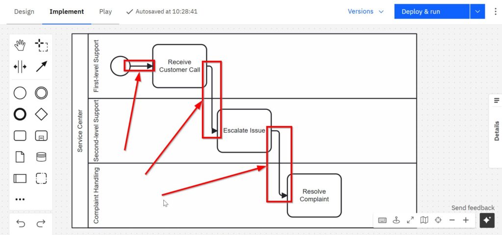
This is normal BPMN behavior.
A Sequence Flow may cross from one Lane to another as long as the activities belong to the same process.
Therefore, I do not use Message Flows for these internal handovers. Message Flows serve communication between separate participants.
Step 5: I Complete the Process with an End Event
Finally, I add an End Event after Resolve Complaint.
The End Event shows that the process instance reaches its defined conclusion after Complaint Handling resolves the case.
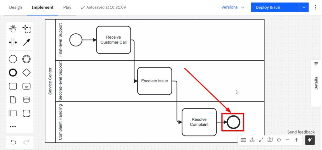
The resulting path is simple:
Customer call arrives. First-level Support receives it. Second-level Support handles the escalation. Complaint Handling resolves the issue. Then the process ends.
The Lane changes also reveal the organizational handovers without adding unnecessary text.
I Keep Flow Nodes Inside Their Lanes
One layout mistake can weaken this clarity quickly. I avoid placing a Task across a Lane boundary.
A Task that visually occupies two Lanes leaves the reader with an obvious question: Which role actually owns it?
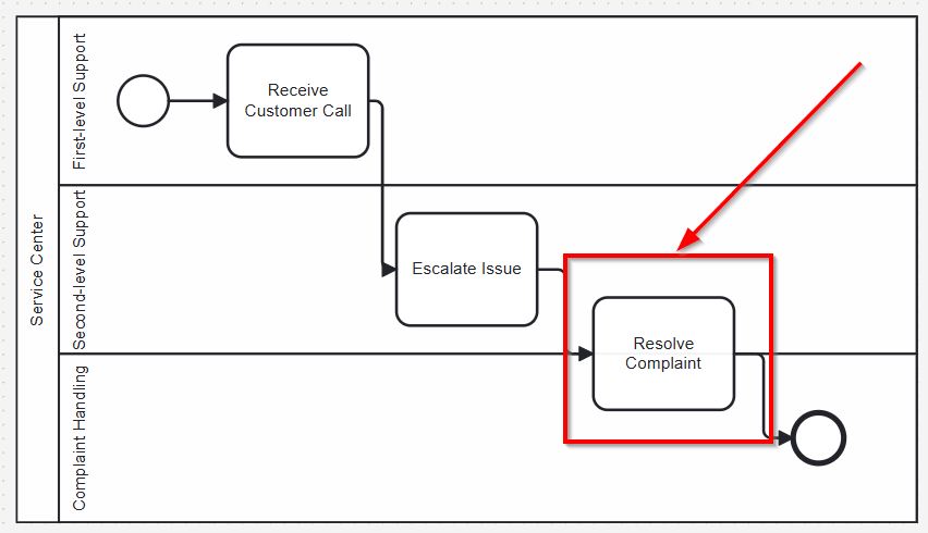
If one activity crosses a Lane boundary visually, I reposition it so that its responsibility remains unambiguous.
I also avoid duplicating the same Task only to suggest shared responsibility. Duplication changes the process model because two Tasks represent two process activities.
Instead, I decide what the collaboration actually means. If two roles perform different parts of the work, I model separate Tasks. If one role remains responsible while another contributes, I keep the Task with the responsible role and document additional responsibilities where appropriate.
When I Use Nested BPMN Lanes
I use true nested Lanes when responsibility has a meaningful hierarchy.
For example, a Service Center may contain a Customer Support area. Customer Support may then contain First-level Support and Second-level Support. In that case, the hierarchy communicates useful organizational information:
Service Center → Customer Support → First-level Support or Second-level Support.
However, I do not reproduce an entire organizational chart in BPMN.
I add Lane hierarchy only when it helps the reader understand process responsibility.
Too many nested levels consume space and make Sequence Flows harder to follow. Therefore, I normally model only the organizational structure that matters for the process.
Groups Are Not a Substitute for Responsibility
BPMN also provides the Group artifact. However, I do not use Groups to assign responsibility.
A Group can visually surround related elements, even across Lanes. Still, it does not change the process flow or determine who performs an activity.
Therefore, I use Groups for visual categorization only. For responsibility, I rely on Lanes and the process structure itself.
A BPMN Group adds visual meaning, but it does not create shared task ownership.
How I Keep Lane-Based Models Readable
I normally arrange the process from left to right. This direction is not a BPMN requirement. However, consistent flow direction makes the diagram easier to scan.
I also keep handovers visible. I avoid unnecessary bends in Sequence Flows, excessive Lane subdivision, and organizational detail that does not affect the process.
As a result, the diagram communicates two things at the same time: what happens and who handles it.
Final Thoughts
BPMN Lanes give me a simple way to connect process behavior with responsibility. I use a Pool for the participant, Lanes for relevant responsibility areas, and Sequence Flows for the process path.
Nested BPMN Lanes add another option. They let me express a hierarchy when one responsibility area contains smaller organizational units. However, I only use that structure when the hierarchy improves the model.
My goal is not to show the maximum possible organizational detail. My goal is to make responsibility clear at the level the process requires.
That principle keeps BPMN diagrams precise, readable, and useful for both process analysis and implementation.
Credits: The diagrams were created with Camunda.
| Read more on Business Process Modeling and Notation (BPMN) |
|---|
| Syntax and Semantics of BPMN BPMN Project Roles for Effective BPM The Participant Perspective in BPMN BPMN Core Elements |