
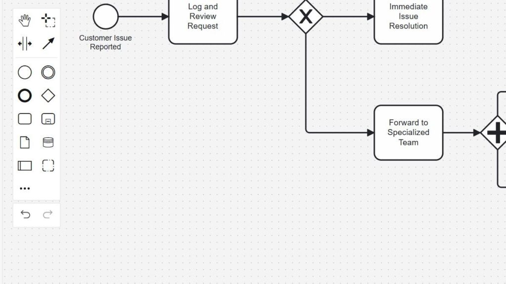
When I first worked with BPMN, process models felt complex. However, Camunda made the structure much easier to understand. In this guide, I show you a clear BPMN example using Camunda. You will build a simple process step by step and see how events, tasks, gateways, and flows work together in practice.
What is Business Process Management?
Before diving into our BPMN example, let’s clarify what Business Process Management (BPM) really means. Simply put, BPM helps organizations analyze, improve, and automate their processes. As a result, workflows become more efficient and transparent. By managing processes well, businesses save time, reduce costs, and enhance customer satisfaction. Read more about Camunda and Process Management in BPMN Lanes in Camunda: A Step-by-Step Guide and How to Create a New Project in Camunda (open in new tabs).
What I Model in This BPMN Example
I use a customer support process because it contains several common BPMN patterns.
A customer first reports an issue. Then, the support team logs and reviews the request. After that, the process determines whether the issue can be resolved immediately.
If the answer is yes, the support team resolves the issue directly.
However, if the issue requires specialist knowledge, the team forwards it. The specialized team then resolves the issue while the customer receives regular updates.
Finally, both paths lead to customer confirmation, feedback, and ticket closure.
This example combines a decision, alternative paths, parallel activities, synchronization, and a clear process end.
Create a New BPMN Diagram
First, I open Camunda Modeler and create a new BPMN diagram.
I start with an empty modeling area. Then, I add the first BPMN element.
Add the Start Event
I select the Start Event from the element palette.
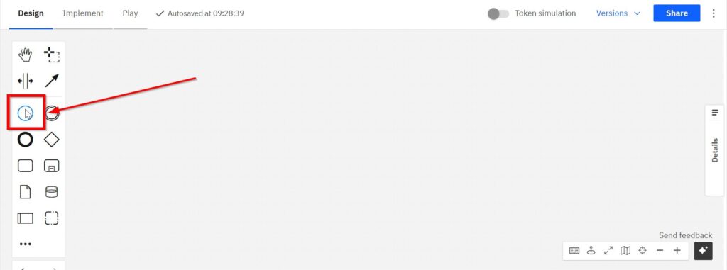
Next, I place the Start Event on the modeling canvas.
I name it “Customer Issue Reported.”
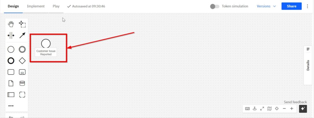
The Start Event defines where the process begins.
I use the Start Event to represent the moment when a new customer issue enters the support process.
Add the First Task
Next, I add the first activity.
I select a Task from the element palette.
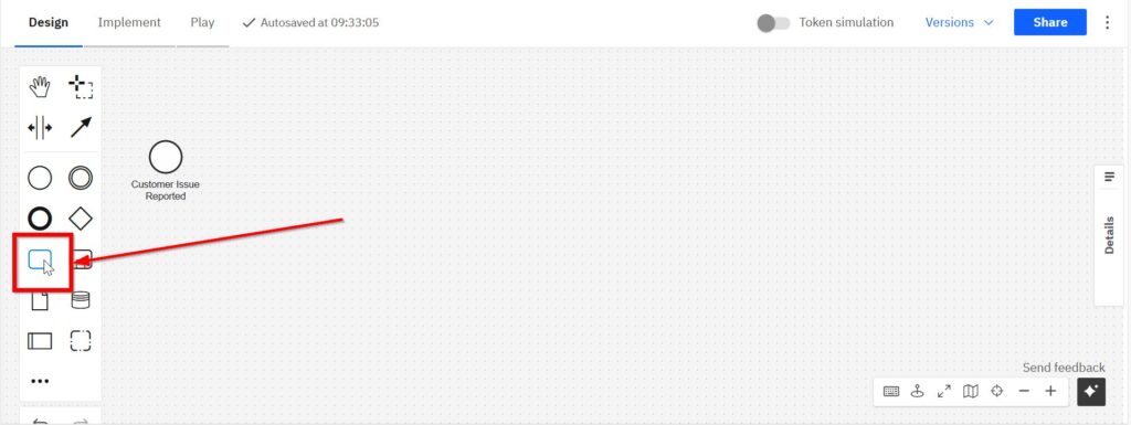
Then, I place the task after the Start Event.
I name it “Log and Review Request.”
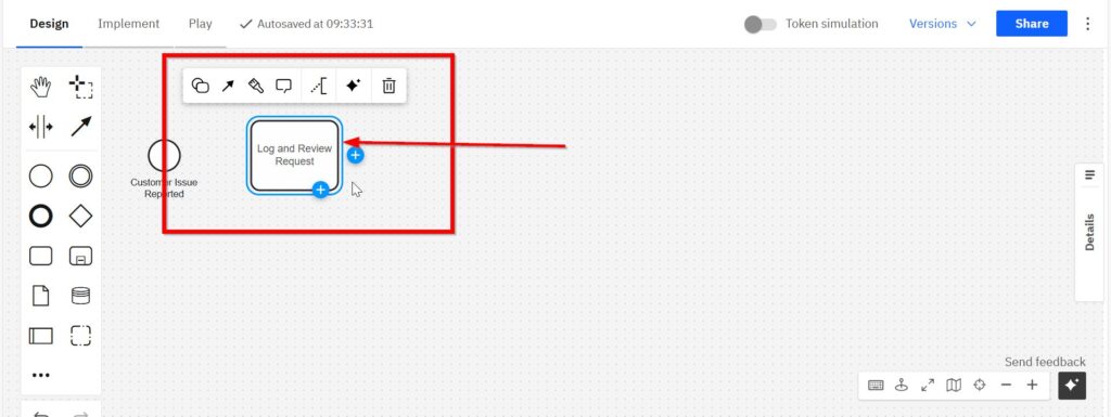
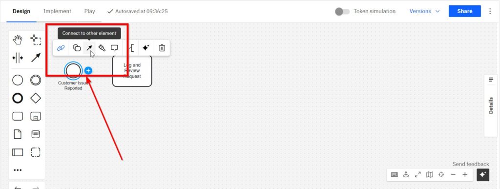
Now I connect the Start Event to the task.
I select the Start Event. Then, I use the sequence-flow control and drag the connection to “Log and Review Request.”
The two elements now form the first process sequence.
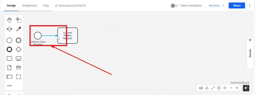
The process currently follows one simple path:
Customer Issue Reported → Log and Review Request
However, the next step depends on the type of issue. Therefore, I now introduce a decision.
Add an Exclusive Gateway
I need to determine whether the support team can resolve the issue immediately.
For this purpose, I use an Exclusive Gateway.
First, I open the additional BPMN elements.
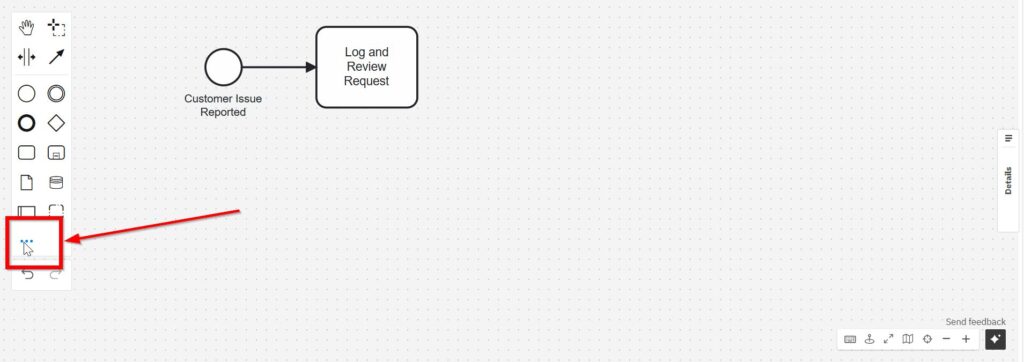
Then, I select “Exclusive Gateway.”
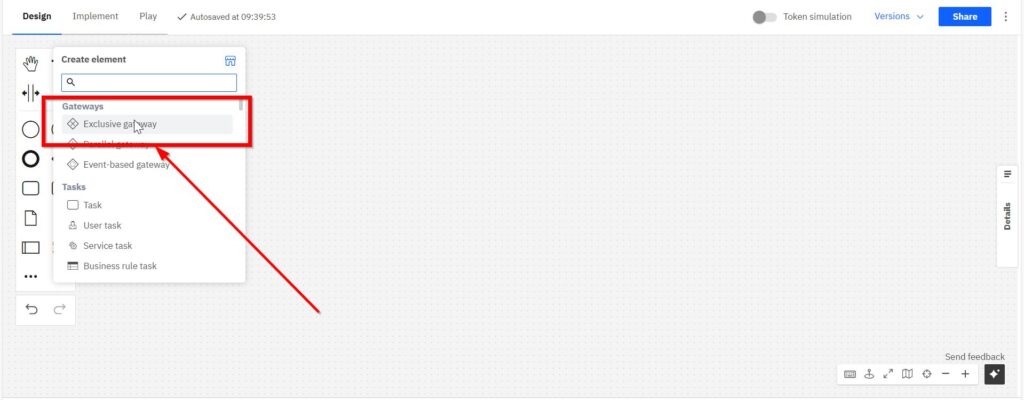
I place the gateway after “Log and Review Request.”
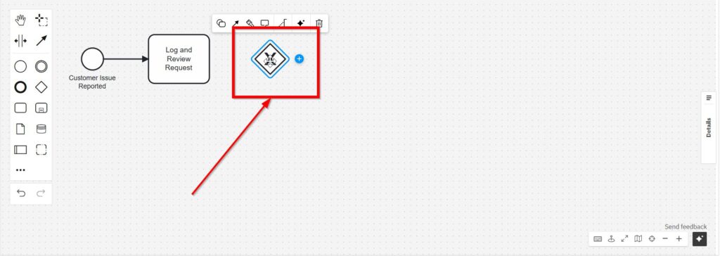
Next, I name the decision:
“Can the Issue be Immediately Resolved?”
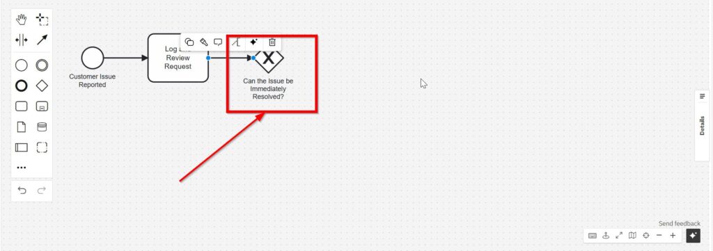
The Exclusive Gateway represents a choice. The process follows one outgoing path based on the result of the decision.
Create the Immediate Resolution Path
First, I model the simple case.
If the support team can solve the issue directly, the process should continue to an immediate resolution task.
Therefore, I add a task named “Immediate Issue Resolution.”
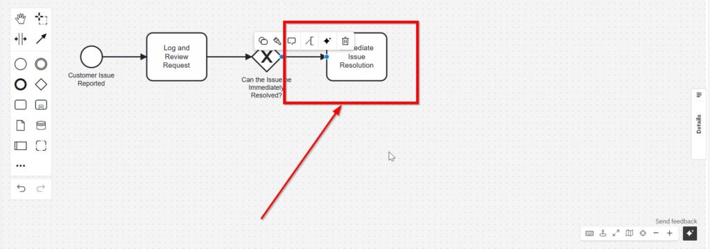
This path represents issues that do not require escalation.
Create the Specialized Resolution Path
Next, I model the alternative.
If the support team cannot resolve the issue immediately, it must forward the request.
Therefore, I create a second outgoing path and add the task “Forward to Specialized Team.”
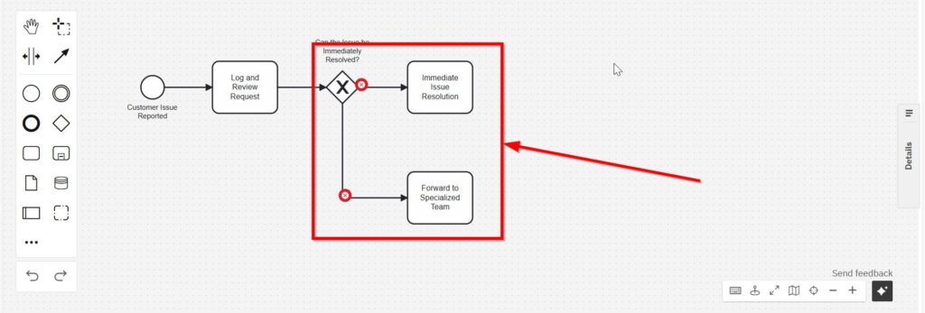
The decision now has two possible outcomes.
However, the diagram alone does not tell Camunda which path to execute. Therefore, I also define conditions.
Configure the Gateway Conditions
I select the sequence flow that leads to the immediate resolution path.
Then, I open its properties.
For this example, I use a process variable named “issueCanBeResolved.”
I define the immediate-resolution path so that it applies when the value is true.
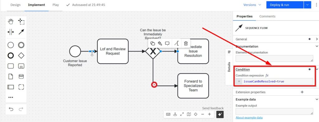
Next, I configure the specialized path.
This path applies when “issueCanBeResolved” is false.
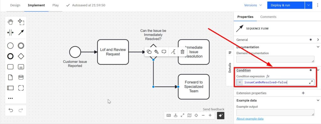
The two conditions represent opposite outcomes of the same business decision.
As a result, the routing logic remains easy to understand.
If the issue can be resolved immediately, the process follows the direct path.
Otherwise, it follows the specialized path.
Add a Parallel Gateway
The specialized team has two responsibilities.
It must resolve the issue. At the same time, the customer should receive regular updates.
Therefore, I model both activities as parallel work.
First, I open the additional BPMN elements again.
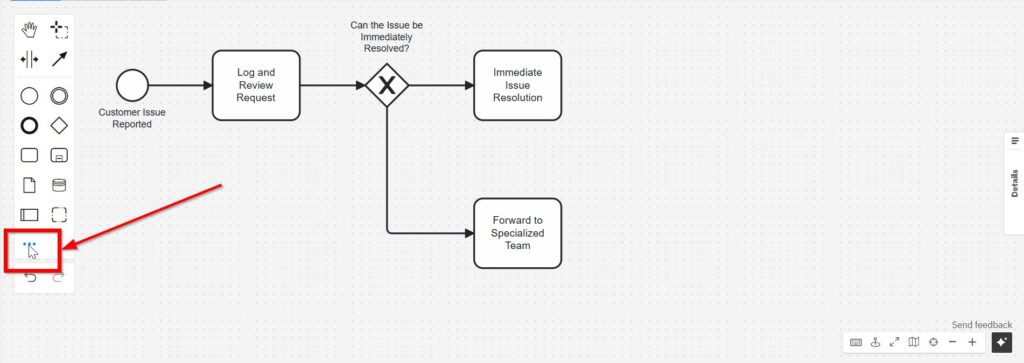
Then, I select “Parallel Gateway.”
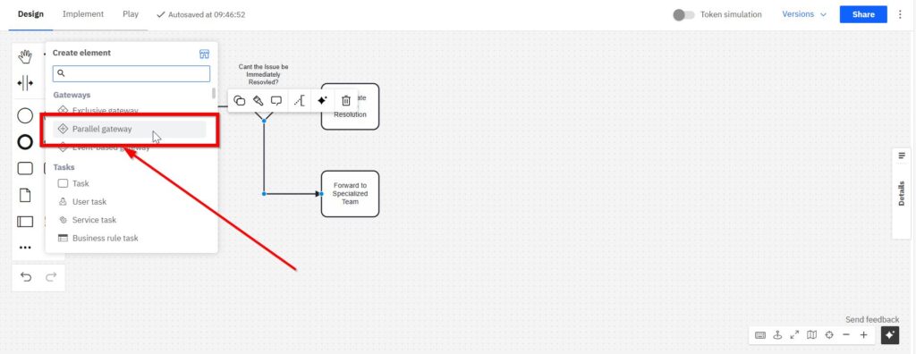
I place the gateway after “Forward to Specialized Team.”
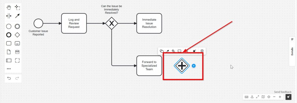
Unlike the Exclusive Gateway, the Parallel Gateway does not choose one path. It activates every outgoing path.
Add the Parallel Activities
I now create two outgoing paths.
The first path represents customer communication.
I add the task “Send Regular Updates to Customer.”
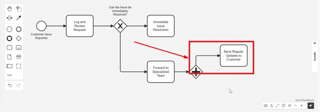
The second path represents the actual specialist work.
I add “Resolve Issue by Specialized Team.”
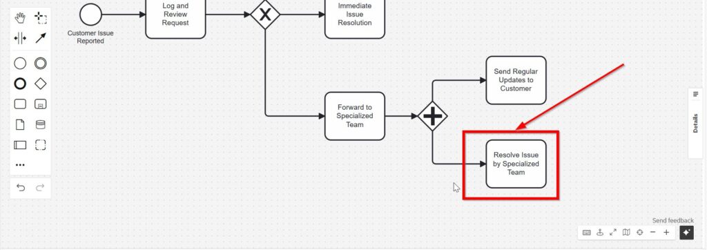
Both activities can now progress independently.
For example, the specialized team does not need to finish its complete investigation before the customer receives an update.
Therefore, the model reflects how the work can occur in practice.
Synchronize the Parallel Paths
However, I cannot simply continue from either parallel activity.
I first need to synchronize both paths.
Therefore, I add another Parallel Gateway after the two tasks.
I connect both parallel activities to this gateway.
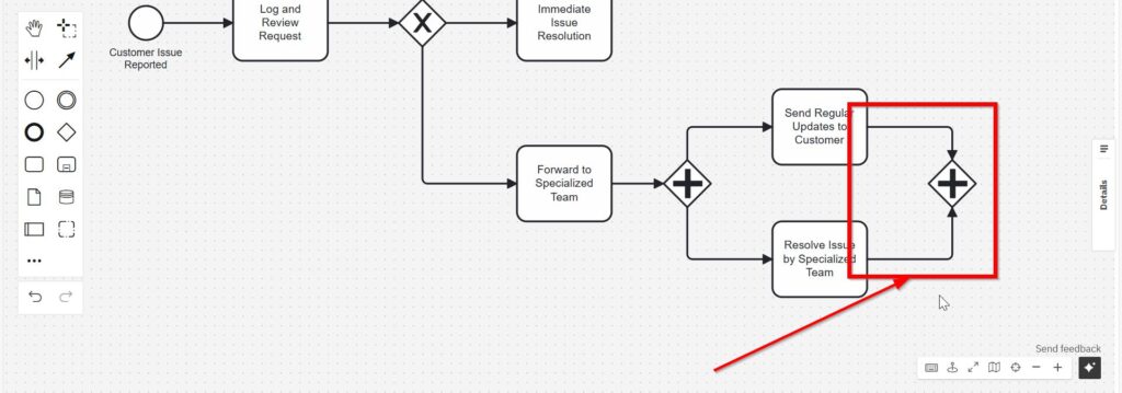
The first Parallel Gateway splits the process.
The second Parallel Gateway joins it again.
The joining Parallel Gateway ensures that the process does not continue until both incoming parallel paths have completed.
This distinction becomes important when later activities depend on the completion of all parallel work.
Confirm the Resolution and Gather Feedback
After synchronization, I continue with the customer-facing closing steps.
First, I add “Confirm Resolution with Customer.”
Then, I add “Gather Customer Feedback.”
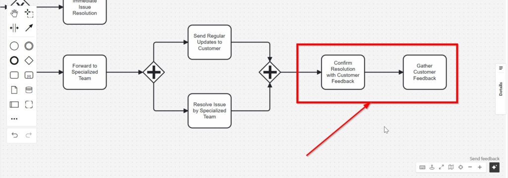
These tasks belong to the final part of the process.
However, I also need to connect the immediate-resolution path to this common sequence.
Therefore, I connect “Immediate Issue Resolution” to “Confirm Resolution with Customer.”
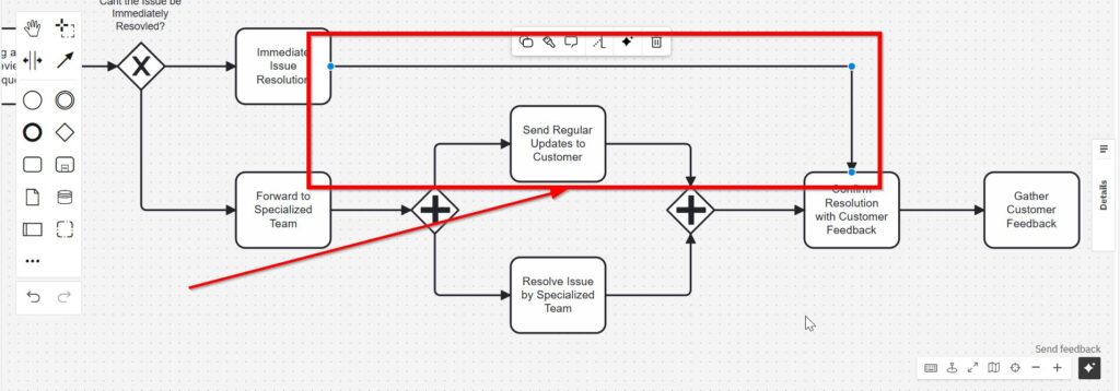
I now have two different resolution paths but only one common closing sequence.
This keeps the model compact.
Moreover, it prevents me from duplicating the same customer confirmation and feedback activities.
Different process paths can converge when they eventually require the same subsequent work.
Add the End Event
Finally, I need a clear endpoint.
I select an End Event from the element palette.
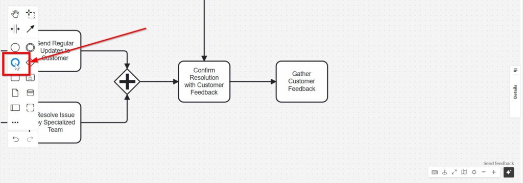
I place it after “Gather Customer Feedback.”
Then, I name it “Close Ticket.”
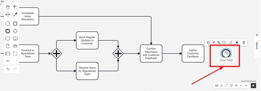
The process now has a clear beginning and a clear end.
It starts when the customer reports an issue.
It ends after the team confirms the resolution, gathers feedback, and closes the ticket.
Review the Complete BPMN Model
The completed workflow combines all of the elements I added during the tutorial.
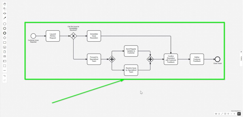
The workflow follows this overall logic:
Customer Issue Reported → Log and Review Request → Resolution Decision.
If the issue can be resolved immediately, the process moves directly to “Immediate Issue Resolution.”
If not, the process moves to “Forward to Specialized Team.”
The specialized branch then starts two parallel activities:
“Send Regular Updates to Customer”
and
“Resolve Issue by Specialized Team.”
After both activities finish, the paths synchronize.
Finally, both resolution alternatives lead to “Confirm Resolution with Customer,” “Gather Customer Feedback,” and “Close Ticket.”
What This BPMN Example Shows
This BPMN example demonstrates three different types of process logic.
First, sequence flows define the order of activities.
Second, the Exclusive Gateway models an alternative.
Only one outgoing path continues.
Third, Parallel Gateways model concurrent work.
All outgoing paths start, and a later Parallel Gateway synchronizes them again.
I use an Exclusive Gateway when the process must choose between alternatives. I use a Parallel Gateway when several activities must proceed without such a choice.
This distinction is fundamental in BPMN.
The model also shows another useful principle.
I do not need to duplicate activities simply because earlier paths differ.
Instead, I can bring alternative paths together when they eventually share the same next steps.
Final Thoughts
I use this customer support example because it combines several important BPMN concepts without creating an unnecessarily large model.
I start with a simple sequence. Then, I introduce a business decision. After that, I model parallel work. Finally, I synchronize the paths and move both resolution alternatives into one common closing sequence.
A clear BPMN model shows not only what happens, but also what happens alternatively, what can happen in parallel, and when the process may continue.
That makes the model useful for discussion, analysis, implementation, and process improvement.
What’s Next?
Now that I have created a practical BPMN example using Camunda, I can improve the process structure. A simple flow helps me understand the logic. However, I also need to show who does what.
Therefore, the next article guides me through BPMN Lanes in Camunda: A Step-by-Step Guide. I will learn how lanes separate responsibilities, roles, teams, or systems inside one process model.
This makes my BPMN diagram easier to read and discuss. As a result, stakeholders can follow the process faster and understand each handover more clearly. Click the next article and continue with a stronger Camunda process structure.
Connect Your Requirements Work with Better Tools and processes
Requirements engineering becomes stronger when I use tools that support clear thinking and practical delivery. In my main article on Requirements Engineering Tools, I show how draw.io, Confluence, Jira, and Camunda work together. I use draw.io to visualize structures and processes.
I use Confluence to document decisions and knowledge. And I use Jira to manage tasks, issues, and progress. Then I use Camunda to model business processes in a clear way. Therefore, this guide helps me choose the right tool for each step of my requirements work.
With these insights, I can also move naturally into the main article on Processes. There, I explore Process Management, BPMN, and Camunda as a practical tool for BPMN modeling. Therefore, I can see how tools and process thinking work together to structure real workflows. Click through to learn how Processes help me model work clearly, improve collaboration, and create stronger business value.
Credits: The diagrams were created with Camunda.
| Read more about Business Process Modeling and Notation (BPMN) |
|---|
| Exclusive Gateways in BPMN 2.0: Clear and Simple Parallel Gateways in BPMN 2.0: Understanding and Using Them Effectively Event-Based Gateways in BPMN 2.0: A Practical Guide Complex Gateways in BPMN 2.0: A Simple Guide |