Creating UML diagrams can feel complicated at first. However, I show how easy it is to build a UML Class diagram with draw.io. Step by step, I guide you through the key parts. As a result, you quickly see which details need close review and which parts you can understand at a glance.
What is draw.io?
Draw.io (opens in a new tab) is a user-friendly online tool for creating various diagrams, including UML class diagrams. It runs directly in your browser, and you don’t need any special software. Moreover, it’s entirely free to use. With draw.io, you can quickly visualize complex systems clearly and efficiently.
Why create class diagrams with draw.io?
When I create class diagrams with draw.io, I find it incredibly straightforward. First of all, the intuitive interface helps me design professional-looking diagrams easily. Secondly, because draw.io is browser-based, I can access my diagrams anywhere. Finally, it supports extensive UML elements, making it perfect for both beginners and experienced professionals.
How to Build a UML Class Diagram with draw.io
Requriements
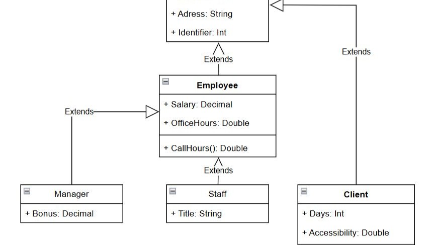
To build a UML Class diagram with draw.io, let’s begin by clearly structuring the class requirements (with at least one attribute for each class):
Parent Class:
- Person
- Attributes:
- Name (String)
- Adresse (String)
- Identifier (Int)
- Attributes:
Subclasses:
- Employee
- Attributes:
- Salary (Decimal)
- OfficeHours (Double)
- Methods:
- CallHours (Double)
- Attributes:
Subsubclasses:
- Manager
- Attributes:
- Bonus (Decimal)
- Attributes:
- Staff
- Attributes:
- Title (String)
- Attributes:
- Client
- Attributes:
- Days (Int)
- Accessibility (String)
- Methods:
- whichStaff() (Double)
- Attributes:
Class without methods
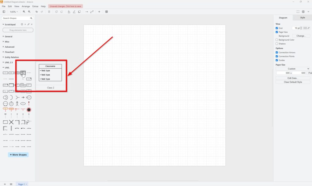
I start by selecting “Class 2” from the UML sidebar for the “Person” class since it doesn’t have methods.
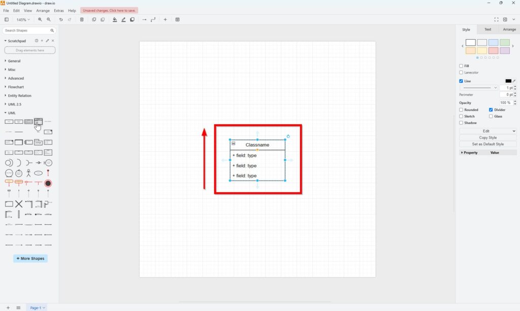
Next, I double-click the class name and rename it “Person.”
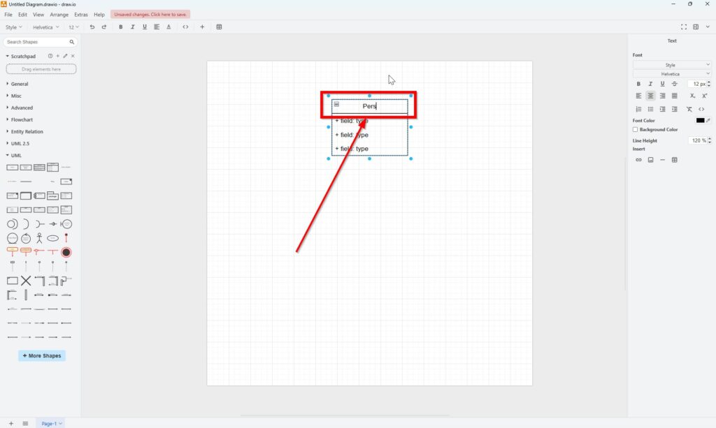
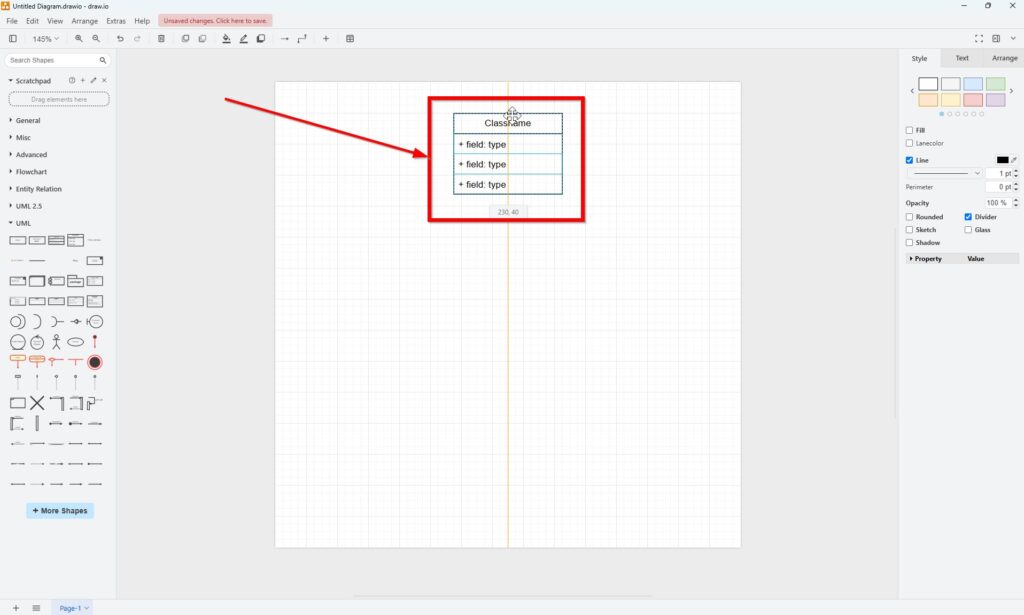
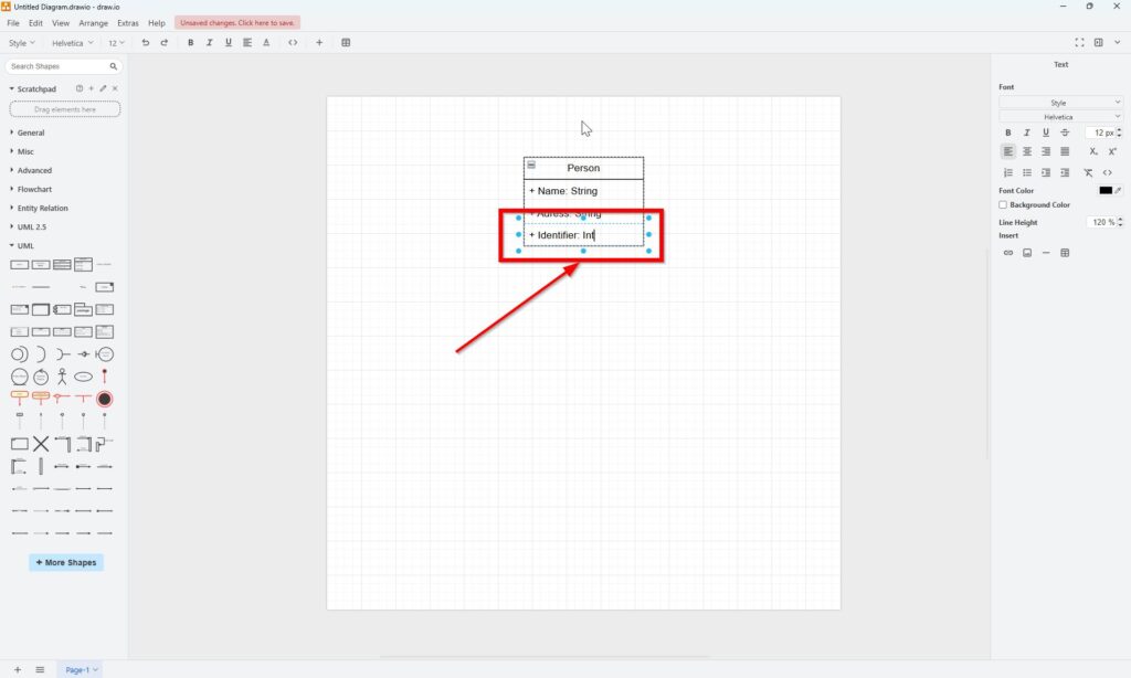
Afterward, I update the attribute fields according to our specifications.
Class with methods
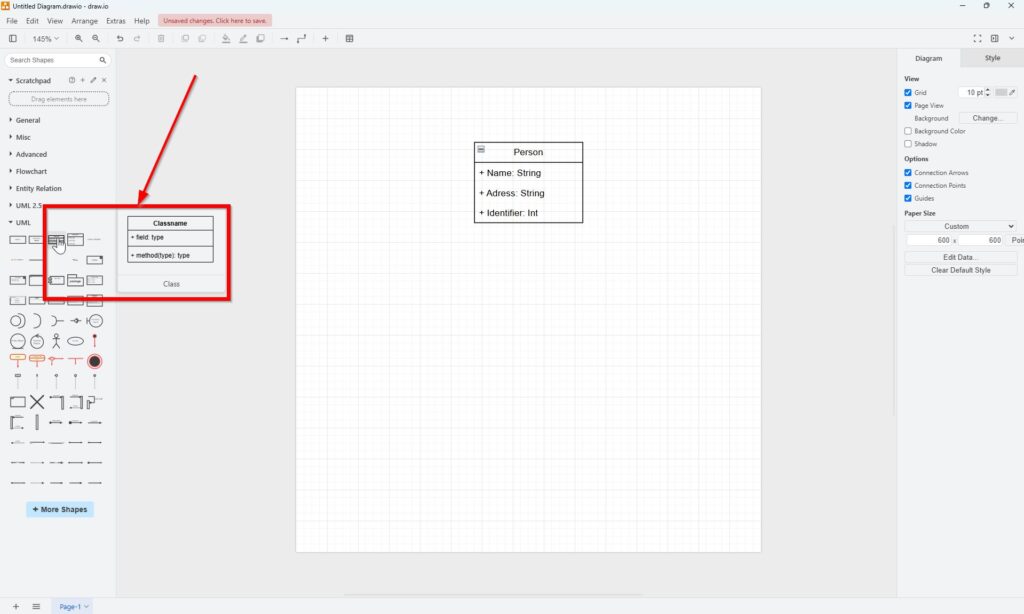
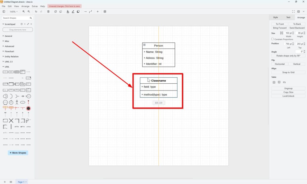
Next, I move to the “Employee” class. Because this class includes a method, I use the regular “Class” element from the draw.io UML sidebar.
If additional attribute fields are needed, I simply click on the existing attribute, then click the small blue arrow that appears. This adds another attribute field instantly.
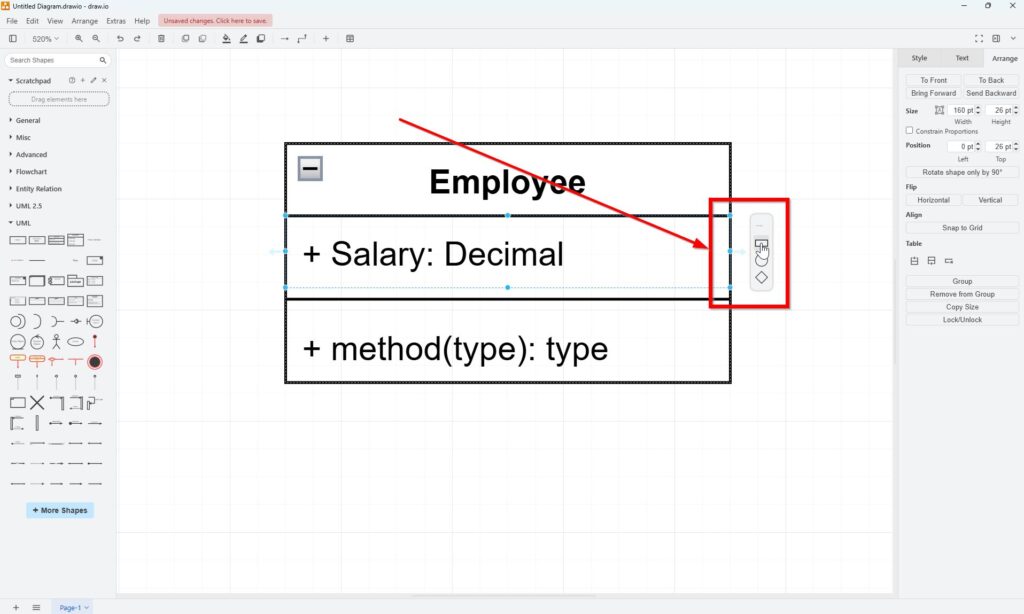
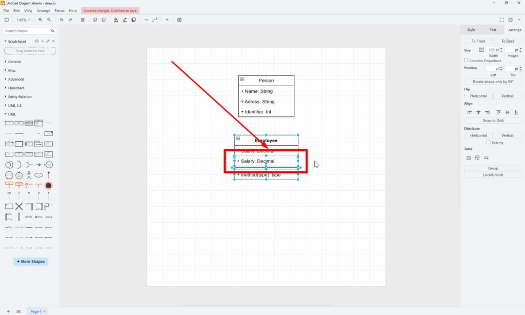
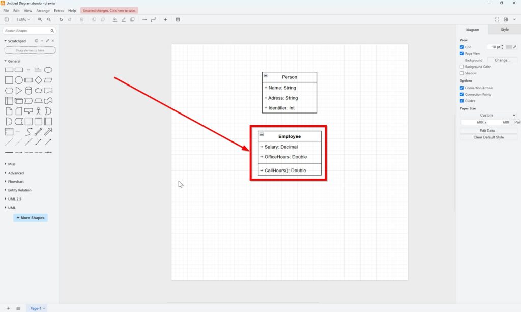
I fill in all fields as defined in the requirements above.
Complete all classes
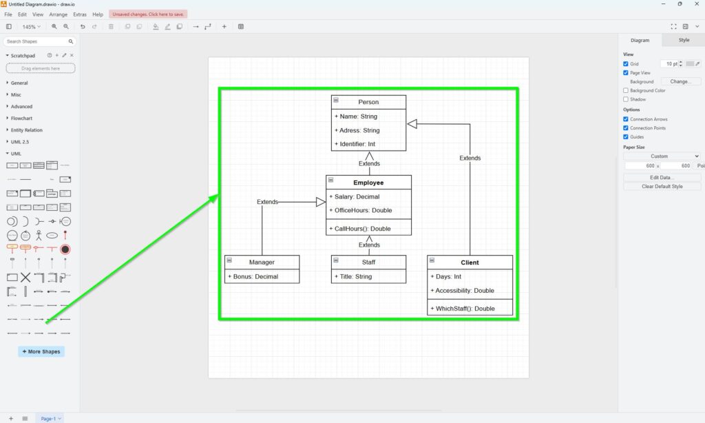
Following this method, I quickly create “Manager” and “Staff” with “Class 2,” as they don’t need methods. For the “Client” class, I select the standard UML “Class” element since it has methods. Feel free to try this yourself and compare your result with my finished diagram.
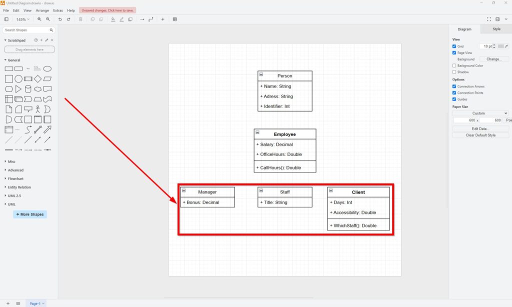
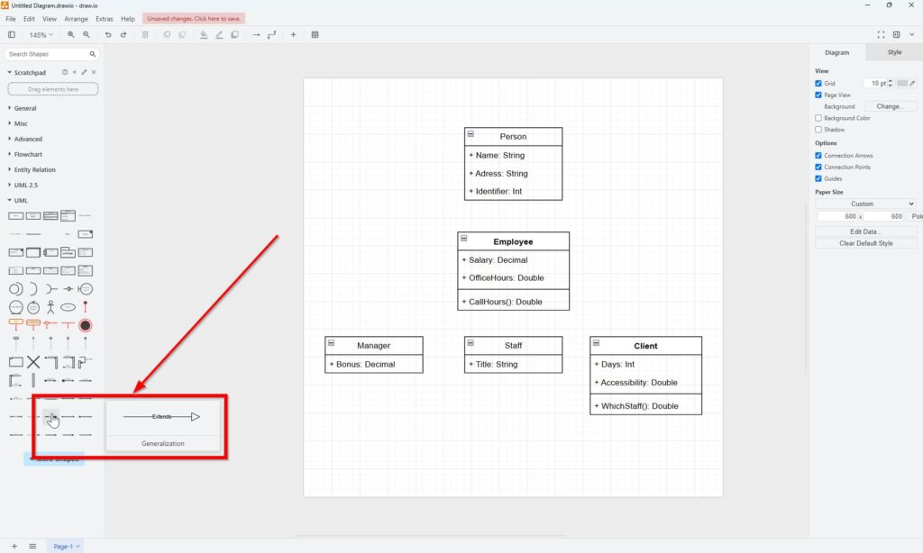
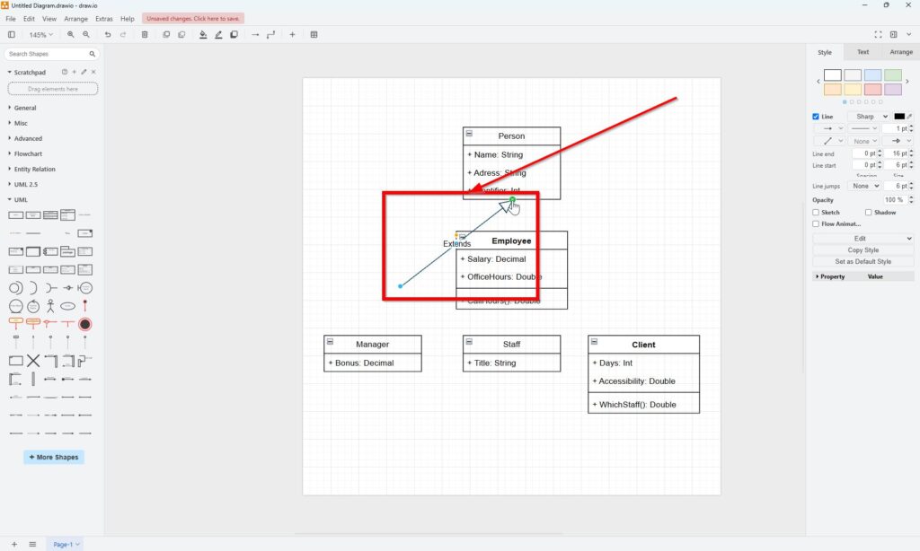
Finally, connecting the classes is simple. Since this structure involves a generalization relationship—indicating inheritance—I use the “Generalization” element from the draw.io sidebar.
The UML class diagram is now finished.
Final Thoughts
Using draw.io to build a UML Class diagram is not just straightforward but also enjoyable. With the steps above, you’ll confidently build a UML class diagram with draw.io on your own in no time. Remember, practice makes perfect, so keep experimenting!
What’s Next?
Now that I know how to build a UML Class diagram with draw.io, I can explore another important UML diagram type. Class diagrams show system structure, but use case diagrams help me understand users, goals, and system interactions. In the next article, I’ll explain Draw UML Use Case Diagrams with draw.io: A Hands-on Example. You’ll learn how actors, use cases, and relationships work together in a clear visual model. Click below to continue and model use cases in draw.io step by step.
Explore Requirements Modeling from Multiple Angles
If I want to understand requirements in a deeper and more practical way, I need more than text alone. I need models that show how concepts, processes, and system structures connect. In the main article on Requirements Modeling, I explore essential Modeling Concepts, Process Modeling with BPMN, and the structural perspective of UML. Together, these topics help me analyze requirements more clearly, communicate them more effectively, and build a stronger foundation for successful system design.
In addition, I also recommend the main article on Requirements Engineering Tools. There, I show how draw.io, Confluence, Jira, and Camunda help me create diagrams, document knowledge, manage work, and model processes in a practical tool workflow.