
Visuals help me understand software systems faster. When I want to show how users interact with a system, I use UML Use Case Diagrams with draw.io. In this post, I guide you through a hands-on example step by step. You’ll learn how actors, use cases, and relationships work together and why execution units matter in system modeling.
What Is a UML Use Case Diagram?
A UML Use Case Diagram describes a system from the perspective of its users and other external participants. Therefore, I use it to answer three basic questions:
- Who interacts with the system?
- Which goals do these actors pursue?
- Which parts of the system support those goals?
The main elements are actors, use cases, associations, and a system boundary.
An actor represents a role that interacts with the system. It can represent a person, another system, or an external service. A use case represents a goal that the system supports for an actor.
A use case describes what the system provides from an external perspective, not how the system implements the behavior internally.
For this example, I model a simple school application. It supports pupils and an administration manager.
Step 1: Create the System Boundary
First, I need a system boundary. I open draw.io and select a rectangle from the General shape library.
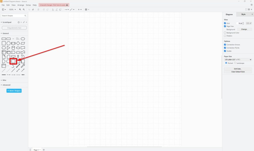
Next, I drag the rectangle onto the canvas.
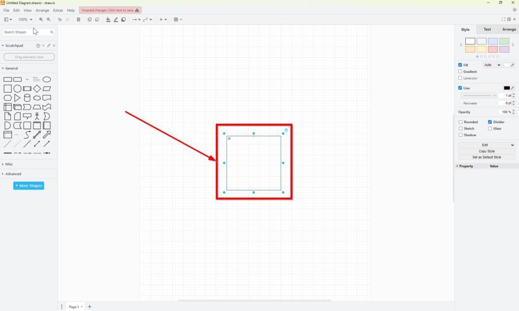
Then, I enlarge the rectangle so that it provides enough space for the use cases.
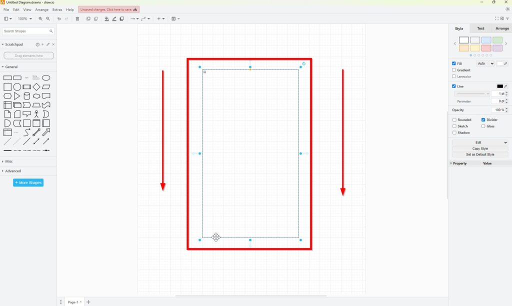
The system boundary separates the modeled system from everything that interacts with it externally.
In a finished UML diagram, I would also give this boundary a clear system name, such as School Management System. That makes the scope explicit.
Step 2: Add the Use Cases
Next, I open the UML shape library and select the oval Use Case element.
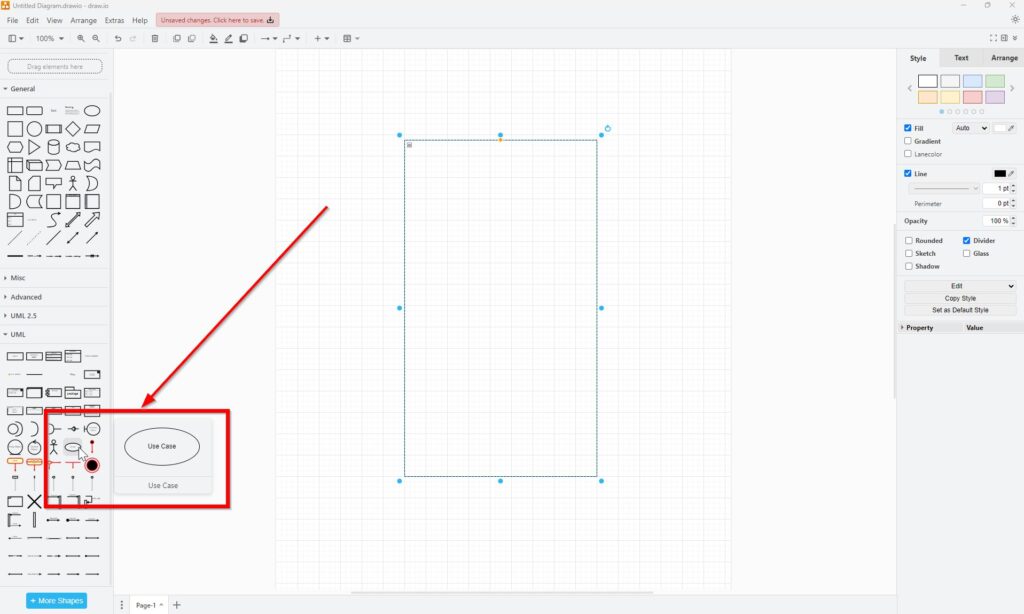
I drag the first use case inside the system boundary.
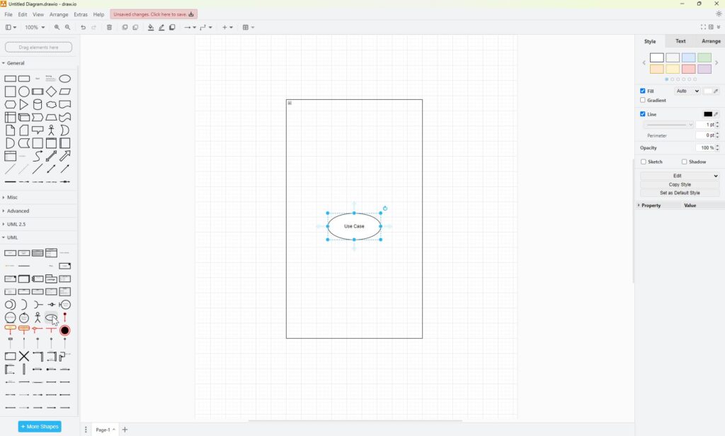
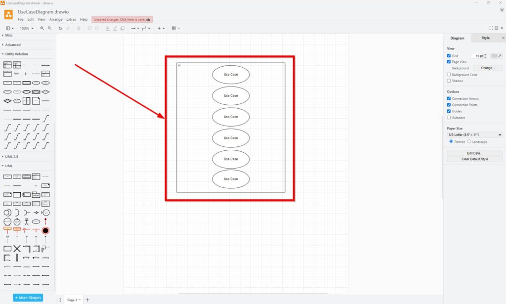
Then, I copy and paste it six times, placing them one under the other inside the rectangle.
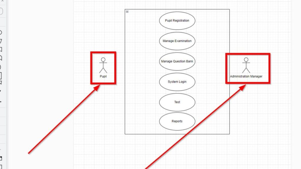
For this school system, the diagram contains these use cases:
- Pupil Registration
- Manage Examination
- Manage Question Bank
- System Login
- Test
- Reports
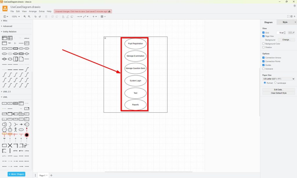
However, I prefer goal-oriented verb phrases in a refined model. For example, I would use Register Pupil, Manage Examinations, Manage Question Bank, Log In, Take Test, and View Reports.
Good use case names describe an actor goal or an observable system service.
This naming rule keeps the diagram focused on behavior. It also prevents use cases from becoming vague labels for screens, database functions, or technical components.
Step 3: Add the Actors
Now I add the external roles.
I select the Actor element from the UML library.
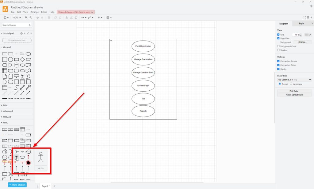
Next, I place one actor on each side of the system boundary. I name them Pupil and Administration Manager.
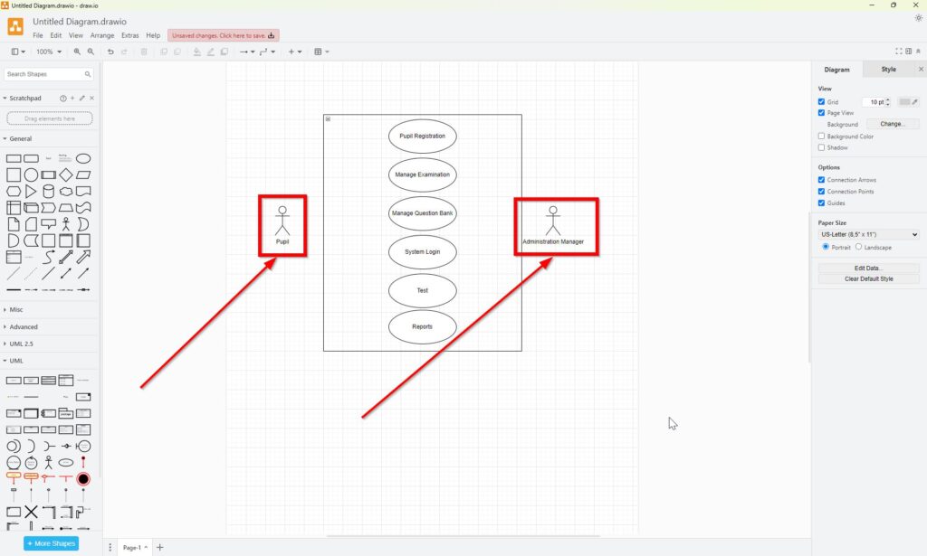
Actors belong outside the boundary because they are not part of the system itself. Instead, they interact with it.
An actor represents a role in relation to the system, not necessarily one specific person.
For example, many individual pupils can perform the Pupil role. Likewise, several employees could potentially act as Administration Manager.
Step 4: Connect Actors and Use Cases
Finally, I connect each actor to the relevant use cases.
A standard association in a UML Use Case Diagram uses a simple solid line. Therefore, I do not need an arrowhead merely to show participation.
In this simplified example, the Pupil interacts with functions such as System Login and Test. The Administration Manager interacts with administrative functions such as Pupil Registration, Manage Examination, and Manage Question Bank.
The exact associations always depend on the real requirements.
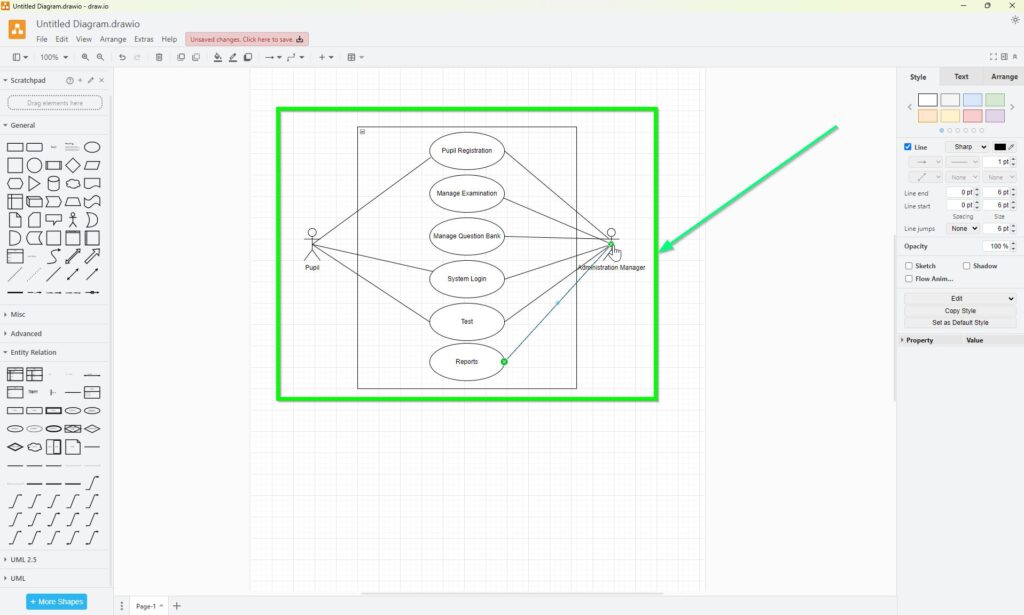
An association means that an actor participates in or communicates with a use case. It does not describe the sequence of actions inside that use case.
This distinction matters. A Use Case Diagram gives me a structural overview of functional interactions. If I need to describe the detailed flow of a use case, I use additional text or another behavioral model.
What the Finished Diagram Tells Me
The finished model immediately shows the system scope, the external roles, and the functionality available to those roles.
For example, I can see:
- which actors interact with the school system;
- which use cases belong inside the system boundary;
- which actor participates in which use case;
- whether important user goals are missing;
- whether a function has no relevant actor.
Therefore, the diagram works well during requirements analysis. It gives stakeholders a compact view without introducing implementation details too early.
Keep Use Case Diagrams at the Right Level
I keep a Use Case Diagram intentionally simple. I do not use it to model screen navigation, algorithms, database operations, or chronological process steps.
Likewise, I do not treat every system function as a separate use case. A useful use case should normally represent something meaningful to an external actor.
The strongest Use Case Diagrams model actor goals and system scope rather than internal technical execution.
UML also provides relationships such as include, extend, and generalization. However, I add them only when they express a real semantic relationship. Adding them merely to make a diagram look more detailed usually reduces clarity.
Conclusion
Creating UML Use Case Diagrams with draw.io requires only a few elements: a system boundary, actors, use cases, and meaningful associations. However, the notation works well only when I model the semantics correctly.
I place actors outside the system, use cases inside it, and connect them according to real participation. Most importantly, I describe user goals rather than technical implementation.
A good Use Case Diagram gives me a clear answer to one central question: who can use the system to a
What’s Next?
Now that I know how UML Use Case Diagrams with draw.io help me show users, goals, and system interactions, I can prepare diagrams for sharing outside the editor. Sometimes I need a printed version for workshops, reviews, or documentation. In the next article, I’ll explain How to Print a Draw.io Diagram. You’ll learn how printing works, which settings matter, and how to create a clean diagram output. Click below to continue and print your draw.io diagram with confidence.
Discover How Requirements Modeling and Tools Turn Ideas into Understanding
If I want to move beyond isolated requirements, I need models that make systems easier to see and explain. In the main article on Requirements Modeling, I explore essential Modeling Concepts, Process Modeling with BPMN, and the structural perspective of UML. Together, these topics help me understand workflows, clarify relationships, and create a more complete picture of the system. Click through to see how Requirements Modeling helps me turn complex requirements into clear, visual, and practical insight.
In addition, I recommend the main article on Requirements Engineering Tools. There, I show how draw.io, Confluence, Jira, and Camunda help me create diagrams, document knowledge, manage work, and model processes in one practical tool workflow.