Software modeling needs clear structure. UML helps me show classes, attributes, operations, and relationships visually. However, I also need to understand what each element means. In this post, I explain Syntax and semantics of UML classes in draw.io. You’ll learn how UML class notation works and how it helps you create clearer software models.
What is UML?
UML (Unified Modeling Language) is a standardized modeling language. It helps software engineers and business analysts visualize and communicate system designs. UML includes different diagram types that describe a system from multiple angles. Among them, a class diagram focuses on structure. It shows classes and how they connect. Within each class, the diagram can show an attribute and an operation. Between classes, it can show a relationship that explains how the classes interact.
What is draw.io?
Draw.io is a free online diagramming tool. It supports UML diagrams, making it easy to design software models. With its drag-and-drop interface, I can quickly create, modify, and share a UML class diagram. It integrates seamlessly with cloud storage services like Google Drive and OneDrive.
Why Model UML with draw.io?
Modeling UML with draw.io is efficient. It offers various UML templates, including class diagrams. Unlike other tools, draw.io is free and does not require installation. It allows customization, ensuring that models align with standard conventions. That is why I prefer using it for UML diagrams.
UML Class Syntax and Semantics with draw.io
Syntax and semantics define the attributes of a UML class. The attributes reside within the class scope. The following elements define them:
Allowed Components
The UML class attributes follow this structure:
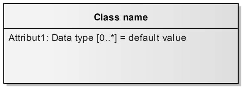
[/] Name [: type] [multiplicity] [= default]
- Name: This is the attribute’s name. It is mandatory.
- Data Type: Specifies the type of the attribute. This is optional.
- Default: Sets a default value for new objects.
- Multiplicity: Defines if an attribute can have multiple values. For example, a person may have multiple first names.
- Derived: A leading / shows that the value is derived. For example, age can be derived from the birthdate.
These attributes define the properties relevant to the system under development.
Mapping UML Class Syntax in draw.io
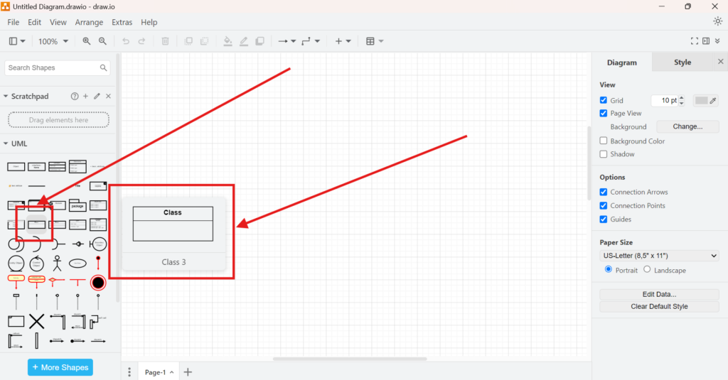
To implement this syntax in draw.io, I use the Class 3 template from the UML templates. Other UML templates exist, but I choose this one because it aligns with IREB (International Requirements Engineering Board) standards.
Step-by-Step Guide
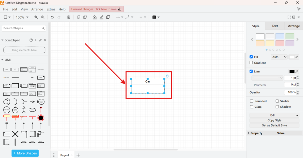
1. Step: Select the Class 3 template and click on it.
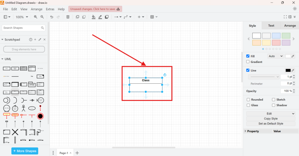
2. Step: Edit the Class Name
I click in the top bar and rename the class to “Car.”
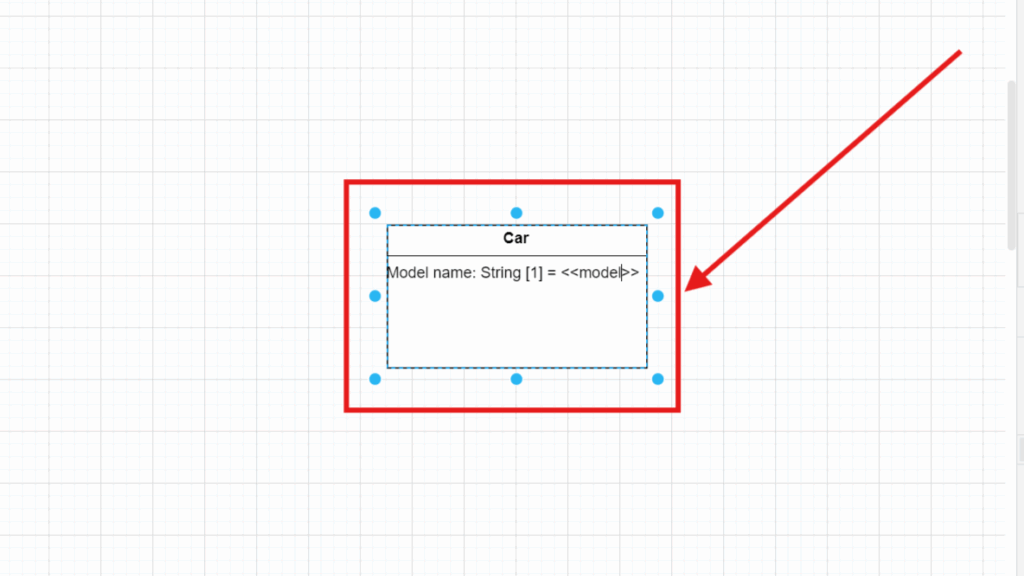
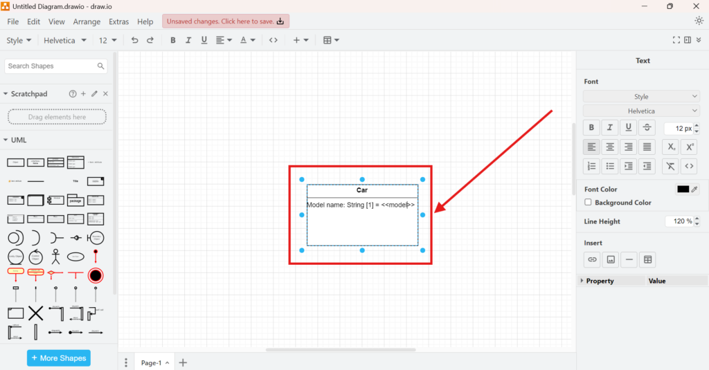
3. Step: Define Attributes
For this example, I define the model name of a car:
- Name: Model name
- Data Type: String
- Default: <<model>>
- Multiplicity: [1] (A car must have exactly one model name)
Just click in the bottom bar and type what you want.
Final Thoughts
Understanding how to model syntax and semantics of UML classes in draw.io is essential for precise system modeling. Draw.io simplifies the process with ready-to-use templates. By following these steps, I ensure that my UML diagrams remain structured and clear. If you are working on software models, try draw.io to create accurate UML class diagrams with minimal effort.
What’s Next?
Now that I understand the syntax and semantics of UML classes in draw.io, I can start modeling classes more practically. Knowing the notation helps, but applying it in a real diagram makes the concept much clearer. In the next article, I’ll explain Model UML Classes in draw.io. You’ll learn how to create UML class elements, structure them clearly, and use draw.io to build more understandable software models. Click below to continue and model UML classes in draw.io step by step.
Discover How Requirements Modeling and Tools Make Complex Systems Easier to Understand
If I want to understand requirements in a clear and practical way, I need more than text alone. I need models that show how concepts, processes, and structures relate to each other. In the main article on Requirements Modeling, I explore Modeling Concepts, Process Modeling with BPMN, and UML to connect these perspectives in one place. As a result, I can visualize workflows, explain relationships, and build a stronger foundation for analysis, communication, and system design.
In addition, I also recommend the main article on Requirements Engineering Tools. There, I show how draw.io, Confluence, Jira, and Camunda help me create diagrams, document knowledge, manage work, and model processes in a practical tool workflow.
This article covers concepts that are also included in the CPRE certification syllabus.