
Creating UML diagrams can seem overwhelming at first, but with the right approach, it becomes much easier. In this article, I’ll share practical tips for UML modeling to help you create clear and meaningful diagrams. These tips for UML modeling focus on avoiding common mistakes, improving consistency, and enhancing communication across teams. By following them, you’ll gain confidence in turning complex ideas into structured visual models that truly represent your system.
1. Add Text When the Diagram Is Not Enough
UML diagrams do not always express every business rule clearly.
Therefore, I add a textual requirement when the graphical model would otherwise become difficult to interpret.
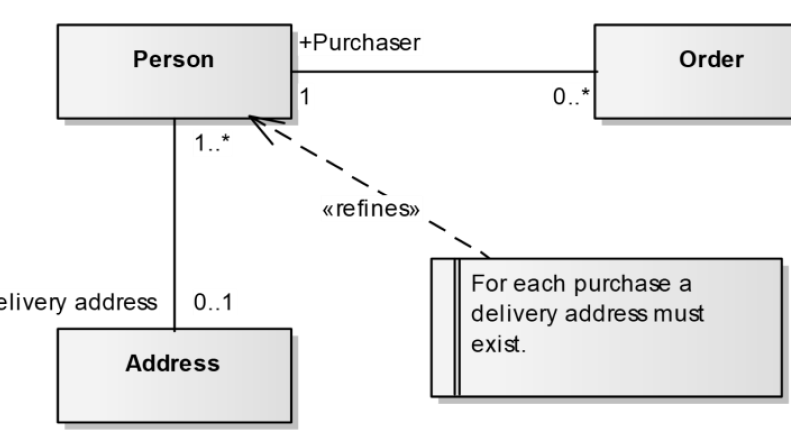
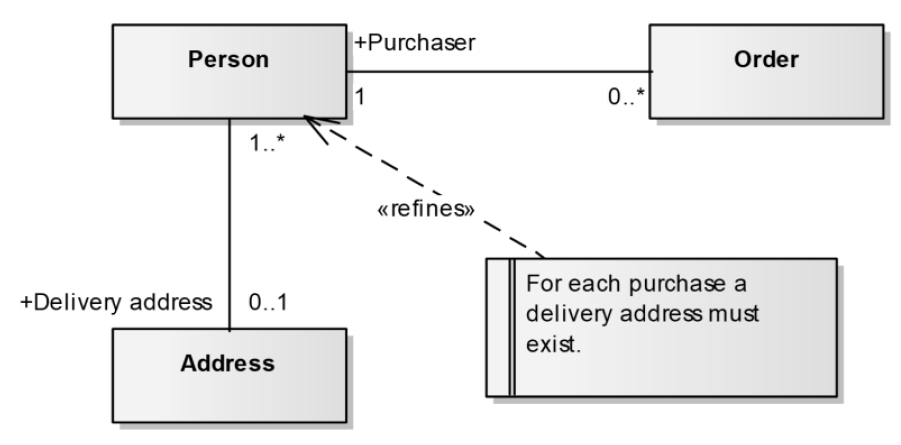
In the example, Person relates to Order and Address. However, the additional requirement states:
“For each purchase a delivery address must exist.”
The text adds a constraint that the relationships alone do not communicate clearly.
I combine UML with text when the requirement becomes clearer than it would be through additional graphical complexity.
2. Question Whether a Separate Class Adds Value
When two concepts have a very simple relationship, I check whether both really need separate classes.
For example, Person and Address can exist as separate classes when Address has its own meaning in the information model.
However, if a concept only represents a simple property of another class, an attribute may be sufficient.
I create a separate class only when the concept has enough independent meaning to justify it.
This keeps the model focused and avoids unnecessary structure.
3. Distinguish Reading Direction From Navigability
Reading direction and navigability look similar, but they express different information.
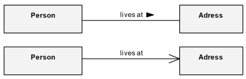
A small triangle next to the association name shows how I read that name.
For example:
Person lives at Address.
Navigability, in contrast, uses an arrow at the association end. It indicates a navigable direction between the model elements.
Therefore, I do not use the two symbols interchangeably.
Reading direction explains how I read the association name, while navigability describes a property of the association itself.
4. Examine Multiplicities Carefully
Multiplicity defines how many objects may participate in an association.
For example, the relationship between Person and Identity Card uses:
- 1 at the Person end
- 0..* at the Identity Card end
This means that one Person can relate to zero or more Identity Cards, while each modeled Identity Card relates to one Person.
However, I do not stop at reading the numbers. I also check whether the multiplicity really represents the requirements.
For example, zero or more identity cards may reflect several valid situations over time.
I treat multiplicity as a domain rule that I need to verify, not simply as a number on the diagram.

Conclusion
Good UML modeling does not mean adding as much notation as possible.
I add text when UML alone becomes unclear. I question unnecessary classes. I separate reading direction from navigability. Finally, I verify multiplicities against the requirements.
My goal is a UML model that communicates the required meaning with as little unnecessary complexity as possible.
What’s Next?!
If I want to improve my UML class models even further, the next step is to choose suitable data types with more care. That is why I continue with Heuristics for Determining Data Types. In that article, I show how I use practical heuristics to assign data types in a structured way. As a result, I can describe attributes more precisely, avoid unnecessary ambiguity, and create UML models that communicate requirements more clearly.
Explore Requirements Modeling in One Connected View
If I want to understand requirements in a clearer and more structured way, I need more than text alone. I need models that show how concepts, processes, and system structures connect. In the main article on Requirements Modeling, I explore Modeling Concepts, Process Modeling with BPMN, and UML to show how each perspective adds value. As a result, I can analyze requirements more effectively, communicate them more clearly, and build a stronger foundation for successful system design.
This article covers concepts that are also included in the CPRE certification syllabus.